


- 6 -
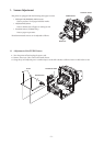
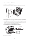
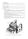
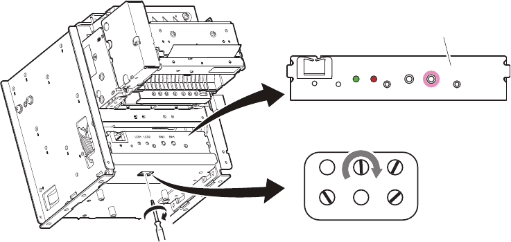
5. Connect the AC adapter and turn the power switch on while pressing switch SW1 on the control panel. e LED
on the control panel will ash two times, then the printer will enter the presenter sensor adjustment mode.
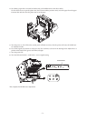
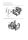
6. Use a small regular screwdriver to slowly turn the VR3 clockwise, as shown in the drawing below. Adjust this to a
position where both LED1 (green) and LED2 (red) light.
If the position where both LED1 (green) and LED2 (red) light, turn VR3 clockwise slowly to adjust to a position
where both LED1 (green) and LED2 (red) light.
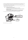
Note: 1) When adjusting, always rotate clockwise.
If rotated in the other direction, accurate adjustment is not possible.
2) Each time the printer enters the presenter paper detection sensor adjustment mode, this
adjustment is necessary.
3) There is a point where the LED ashes instantly. That is not an adjustment position.
There is a point where the LED lights completely. That is the adjustment position.
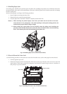
7. Turn the power OFF. Turn the DIP switch DSW 1-4 and DSW 1-5 to its original setting.
is completes the Presenter sensor adjustment.
LED1
LED2
SW2 SW1
Control Panel