4
S93WD462/S93WD463
2029 2.2 1/23/01
SUMMIT MICROELECTRONICS, Inc.
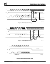
Erase
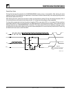
Upon receiving an ERASE command and address, the
CS (Chip Select) pin must be deselected for a minimum
of 250ns (t
CSMIN
). The falling edge of CS will start the
auto erase cycle of the selected memory location. The
ready/busy status of the S93WD462/WD463 can be
determined by selecting the device and polling the DO
pin. Once cleared, the content of a cleared location
returns to a logical “1” state.
Erase/Write Enable and Disable
The S93WD462/WD463 powers up in the write disable
state. Any writing after power-up or after an EWDS
(write disable) instruction must first be preceded by the
EWEN (write enable) instruction. Once the write in-
struction is enabled, it will remain enabled until power to
the device is removed, or the EWDS instruction is sent.
The EWDS instruction can be used to disable all
S93WD462/WD463 write and clear instructions, and
will prevent any accidental writing or clearing of the
device. Data can be read normally from the device
regardless of the write enable/disable status.
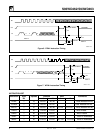
Page Write
93WD462 - Assume WEN has been issued. The host
will then take CS high, and begin clocking in the start
bit, write command and 7-bit address immediately
followed by the first byte of data to be written. The host
can then continue clocking in 8-bit bytes of data with
each byte to be written to the next higher address.
Internally the address pointer is incremented after
receiving each group of eight clocks; however, once
the address counter reaches xxx 1111 it will roll over
to xxx 0000 with the next clock. After the last bit is
clocked in no internal write operation will occur until CS
is brought low.
93WD463 - Assume WEN has been issued. The host
will then take CS high, and begin clocking in the start
bit, write command and 6-bit address immediately
followed by the first 16-bit word of data to be written.
The host can then continue clocking in 16-bit words of
data with each word to be written to the next higher
address. Internally the address pointer is incremented
after receiving each group of sixteen clocks; however,
once the address counter reaches xxx x111 it will roll
over to xx x000 with the next clock. After the last bit is
clocked in no internal write operation will occur until CS
is brought low.
Continuous Read
This begins just like a standard read with the host
issuing a read instruction and clocking out the data
byte [word]. If the host then keeps CS high and
continues generating clocks on SK, the S93WD462/
WD463 will output data from the next higher address
location. The S93WD462/WD463 will continue
incrementing the address and outputting data so long
as CS stays high. If the highest address is reached, the
address counter will roll over to address 0000. CS
going low will reset the instruction register and any
subsequent read must be initiated in the normal man-
ner of issuing the command and address.
Erase All
Upon receiving an ERAL command, the CS (Chip Se-
lect) pin must be deselected for a minimum of 250ns
(t
CSMIN
). The falling edge of CS will start the self clocking
clear cycle of all memory locations in the device. The
clocking of the SK pin is not necessary after the device
has entered the self clocking mode. The ready/busy
status of the S93WD462/WD463 can be determined by
selecting the device and polling the DO pin. Once
cleared, the contents of all memory bits will be in a
logical “1” state.
Write All
Upon receiving a WRAL command and data, the CS
(Chip Select) pin must be deselected for a minimum of
250ns (t
CSMIN
). The falling edge of CS will start the self
clocking data write to all memory locations in the device.
The clocking of the SK pin is not necessary after the
device has entered the self clocking mode. The ready/
busy status of the S93WD462/WD463 can be deter-
mined by selecting the device and polling the DO pin. It
is not necessary for all memory locations to be cleared
before the WRAL command is executed.


