


Troubleshooting Overview 9-7
9
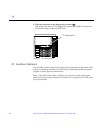
9.3 Basic Definitions for the Card Cage
When locating a board slot in the 8-slot and 16-slot card cages, remember:
9.4 Diagnosing Problems
When board LED codes indicate a hardware problem, several types of software
programs are available to supply information about the problem.
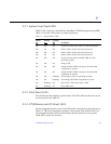
9.4.1 Error Messages
Error messages and other system messages are saved in the file
/var/adm/messages.
Slot numbers Even-numbered slots are at the front of the card cage. Odd-
numbered slots are at the back.
In the front of the card cage, even-numbered slots begin with slot
0 at the top. At the rear of the card cage, odd-numbered slots
begin with slot 1 at the top.
Install the boards with component side down in the front slots and
with component side up in the rear slots.
For specific slot numbers, see Appendix B, “Functional
Description.”
Slot functions All card cage slots are equivalent. However, for convenience in
installing I/O cables, it is suggested that you install
CPU/Memory boards at the front of the cage and install I/O
boards at the back of the cage. When all slots are filled on one
side of the cage, you can use the other side.
Slot 1 should contain an I/O board connected to the boot disk.
(This is not a requirement.)
Slot 0 should contain a CPU/master board with at least one CPU.
The POST diagnostics display more messages if slot 0 contains a
CPU/Memory board and a CPU. For an explanation, see the next
item, “Master board.”
Master board There is no master board during normal system operations. The
first CPU/Memory board (in slot 0) functions temporarily as a
master board during some POST tests.