


D-2 Ultra Enterprise 6000/5000/4000 Systems Manual—November 1996
D
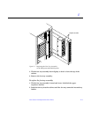
2. Install I/O boards at the rear of the system to facilitate I/O cable
attachments.
3. If you require additional slots, you may use those at the front of the card
cage, preferably below the CPU/Memory boards.
4. Up to four graphics (UPA) cards are supported in a system. (Maximum)
5. The I/O board in slot 1 of any Enterprise server must be terminated because
it connects to the SCSI tray. (Requirement)
6. An I/O board in a slot other than slot 1 does not require termination if no
devices connect to the SCSI bus on that board.
D.1.3 Disk Board
1. The 16-slot Enterprise 6000 system supports up to two Disk boards.
(Maximum)
a. Disk boards are supported only in slots 14 and 15.
b. Slot 15 must be used when installing only one Disk board.
2. The 8-slot Enterprise 5000 and 4000 systems support up to four disk boards.
(Maximum)
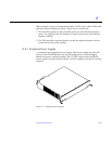
3. The disk board has a capacity of two disk drives. In addition to the three
status LEDs found on other types of boards, the disk board has two LEDs to
show the status of the individual disk drives. LEDs 1 and 2 represent drives
0 and 1, respectively.
D.1.4 Power Supplies and Fan Cooling
1. The fans in the power/cooling modules (PCMs) provide cooling air only for
the two adjacent board slots. Do not install a board in a slot that is not
cooled by a PCM. (Requirement)
2. You must fill all empty slots (board slots and power supply slots) to avoid
loss of cooling air to the active boards. (Requirement) For further
information on this subject, see Section D.1.5, “Filler Panels and Load
Boards.”