S16A User’s Guide Hardware Interface
EDT, Inc. October, 1996 25
Connector Pinout
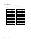
The S16A uses a 37-pin D connector, such as an AMP 748878-1.
The following pinout diagram describes the connection from the S16A board to the cable.
NOTE: Do not connect your own circuits to the unused pins, as they may be internally
connected to the S16A.
Pin Signal Pin Signal
1 DIO00 20 DIO01
2 DIO02 21 DIO03
3 Ground 22 Ground
4 DIO04 23 DIO05
5 DIO06 24 DIO07
6 Ground 25 Ground
7 DIO08 26 DIO09
8 DIO10 27 DIO11
9 Ground 28 Ground
10 CH0OUT 29 Ground
11 Ground 30 CH0INP
12 CH0INM 31 Ground
13 Ground 32 Reserved
14 Reserved 33 Ground
15 Ground 34 CH1INP
16 CH1INM 35 Ground
17 Ground 36 CH1OUT
18 Ground 37 Ground
19 UVCC
Table 5. Connector Pinout


