S16A User’s Guide Registers
EDT, Inc. October, 1996 31
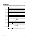
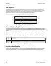
Analog Input Module Internal Registers
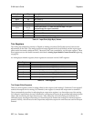
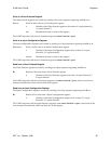
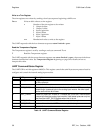
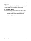
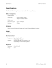
The Analog Input Module contains 11 internal registers, described in the following sections, that control the
analog input and other settings. These registers are accessed using the two UART registers described in the
section Analog Input Module UART Registers beginning on page 34.
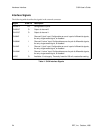
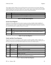
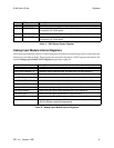
Bit S16A_ Description
0 OUT0_ENABLE Enables I/O channel 0 output
1 OUT0_20BIT When set, configures I/O channel 0 as 20-bit digital-to-analog; when clear,
the channel is in 16-bit mode.
4 OUT1_ENABLE Enables I/O channel 1 output
5 OUT1_20BIT When set, configures I/O channel 1 as 20-bit digital-to-analog; when clear,
the channel is in 16-bit mode.
Table 11. DAC Output Control Register
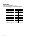
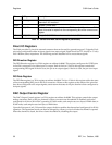
Name Description
Input Clock Prescale 0 In Provides a divisor from the base 192 KHz clock for input channel 0.
Input Clock Prescale 1 In Provides a divisor from the base 192 KHz clock for input channel 1.
Input Configuration 0 In Controls the input source and the gain for input channel 0.
Input Configuration 1 In Controls the input source and the gain for input channel 1.
Trim Output Offset 0 Controls the output voltage offset adjustment for output channel 0.
Trim Output Offset 1 Controls the output voltage offset adjustment for output channel 1.
Trim Input Gain 0 Controls the input gain adjustment for input channel 0.
Trim Input Offset 0 Controls the input level offset adjustment for input channel 0.
Trim Input Gain 1 Controls the input gain adjustment for input channel 1.
Trim Input Offset 1 Controls the input level offset adjustment for input channel 1.
Temperature Two-byte register containing a 12-bit temperature reading for calibrating the
S16A for different operating temperatures.
Table 12. Analog Input Module Internal Registers


