Registers S16A User’s Guide
28 EDT, Inc. October, 1996
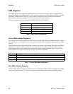
DMA Registers
The S16A provides four independent DMA channels: one each for input and output for each of the two
analog I/O channels. Each DMA channel can be accessed to set up a new DMA transfer while it is currently
performing a DMA transfer. When the current transfer completes the new one begins automatically
without pause, allowing non-stop I/O on both I/O channels in both directions.
The following table shows the assignment of DMA channels to I/O channels.
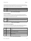
Current DMA Address Registers
The Current DMA Address registers are 32-bit read-only registers at addresses 0x40000, 0x40010, 0x40020,
and 0x40030, one for each DMA channel. The second-lowest hexadecimal address digit specifies the DMA
channel.
These registers hold the address of the DMA currently in progress for each channel. When the current DMA
transfer on a channel completes, if there is a “next” one set up, the contents of the Next DMA Address
register for the channel are copied to the Current DMA Address register, the next count is copied to the
Current DMA Count register, and the new transfer is started automatically.
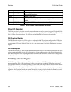
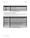
Next DMA Address Registers
The Next DMA Address registers are 32-bit registers at addresses 0x40004, 0x40014, 0x40024, and 0x40034,
one for each DMA channel. The second-lowest hexadecimal address digit specifies the DMA channel.
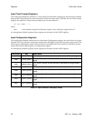
DMA Channel Use
0 Analog I/O channel 0 Input
1 Analog I/O channel 1 Input
2 Analog I/O channel 0 Output
3 Analog I/O channel 1 Output
Table 6. DMA Channel Assignments
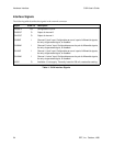
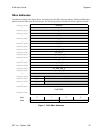
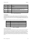
Bit Description
31–20 The 1 MB page addressed by the DMA.
19–2 When read, the next address to access on the SBus.
1–0 Always 0. S16A DMA transfers must be 32-bit word-aligned.
Table 7. Current DMA Address Registers


