S16A User’s Guide Registers
EDT, Inc. October, 1996 33
Trim Registers
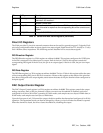
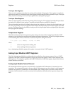
The Analog Input Module contains six Digital-to-Analog converters (DACs) that control various trim
adjustments on the S16A. The analog input and output signals can be level-shifted, and the input signal
gains can be fine-tuned with these DACs. These trim DACs are controlled by six 8-bit trim registers. These
trim registers are set with the D command, described in Analog Input Module Control Protocol beginning
on page 34.
As Analog Input Module registers, these registers are accessed via the UART registers.
Trim Output Offset Registers
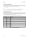
These two trim registers control a voltage offset for the output of each analog I/O channel. Trim register 2
controls the output trim for analog I/O channel 0; trim register 3 controls the output trim for channel 1.
The recommended procedure for adjusting these output trim registers is to first adjust one of the analog
I/O channels’ input offset to be zero-calibrated by configuring its input to be ground and adjusting its input
offset while monitoring the input data for zero. After setting up one of the analog I/O channels as a
calibrated input, reconfigure the analog I/O channel input to monitor the analog I/O channel output in
question. Finally, with all zeros for the output data, adjust the output trim until zeros are read in the input
channel.
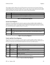
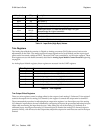
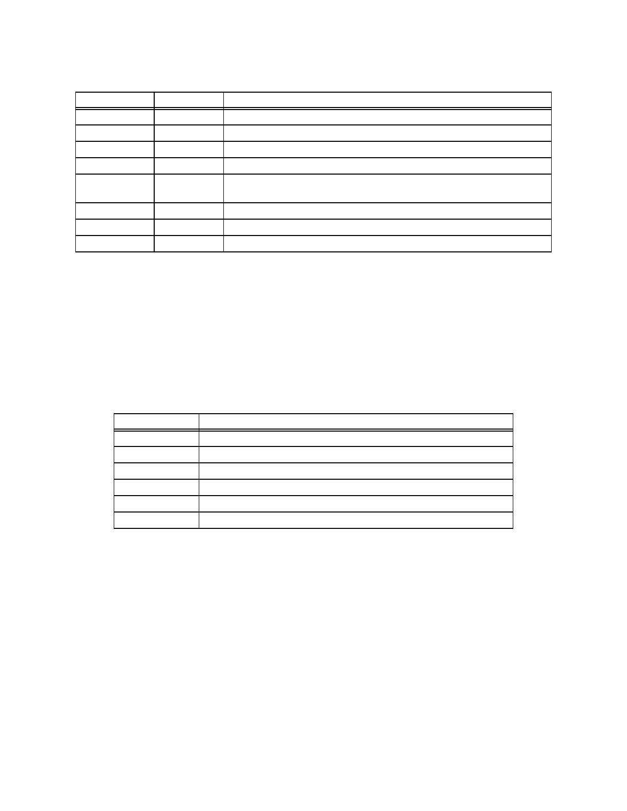
Value (hex) AIN_ Description
08
xx
X1 Unit gain.
09
xx
X2 Gain factor 2.
0A
xx
X5 Gain factor 5.
0C
xx
X10_1 First gain factor 10. Uses the first-stage gain at maximum.
10
xx
X10_2
Second gain factor 10. Uses the second-stage 10 x gain.
Recommended for higher bandwidth.
11
xx
X20 Gain factor 20.
12
xx
X50 Gain factor 50.
14
xx
X100 Gain factor 100. Uses both stages at maximum.
Table 14. Input Gain (High Byte) Values
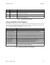
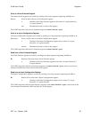
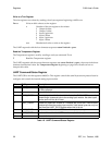
Trim Register Use
2 controls the output trim for analog I/O channel 0
3 controls the output trim for analog I/O channel 1
4 controls the input gain trim for analog I/O channel 0
5 controls the input offset for analog I/O channel 0
6 controls the input gain trim for analog I/O channel 1
7 controls the input offset for analog I/O channel 1
Table 15. Trim Registers


