


5-16
A+ SERVER 1022G-UTF User's Manual
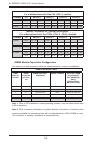
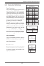
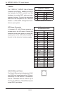
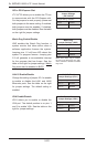
T-SGPIO
The T-SGPIO1/ T-SGPIO2 (Serial General
Purpose Input/Output) headers provide a
bus between the SATA controller and the
backpane to provide SATA enclosure man-
agement functions. Connect the appropriate
cable from the backplane to the T-SGPIO1
header to utilize SATA management func-
tions on your system.
SGPIO Header Pin Denitions
(T-SGPIO1/T-SGPIO2)
Pin# Denition Pin# Denition
1 NC 2 Data In
3 Ground 4 Data Out
5 Load 6 Ground
7 Clock 8 NC
Note: NC indicates no connection.
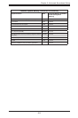
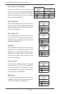
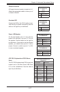
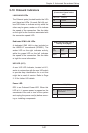
UIO Power Connector
A Universal I/O (UIO) Power connector is
located next to the UID switch. Connect this
connector to the power supply to provide ad-
equate power to the UIO device installed on
the slot for this device to function properly.
UIO Power Connector
Pin Denitions (UIOP)
Pin# Denition Pin# Denition
B1 5V_1 A1 3V3_1
B2 5V_2 A2 3V3_2
B3 5V_3 A3 3V3_3
B4 5V_4 A4 3V3_4
B5 5V_5 A5 3V3_5
B6 5V_6 A6 3V3_6
B7 5V_7 A7 3V3_7
B8 5V_8 A8 3V3_8
B9 5V_9 A9 3V3_9
B10 5V_10 A10 3V3_10
B11 N12V A11 3V3
B12 3V3_STBY A12 3V3
B13 3V3_STBY A13 P12V_2
B14 GND A14 P12V
B15 GND A15 P12V
B16 GND_1 A16 P12V
B17 GND_2 A17 P12V
B18 GND_3 A18 GND_7
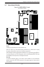
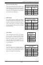
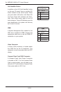
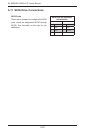
LAN1/2 (Ethernet Ports)
Two Gigabit Ethernet ports (designated LAN1
and LAN2) are located beside the VGA port.
Additionally, for the H8DGU-F serverboard,
there is a dedicated LAN for IPMI on top of
the two rear USB ports. These Ethernet ports
accept RJ45 type cables.