


Chapter 5: Advanced Serverboard Setup
5-9
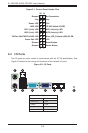
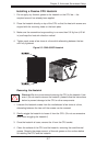
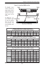
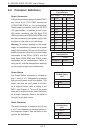
Figure 5-4. Installing DIMM into Slot
To Install: Insert
module vertically and
press down until it
snaps into place. Pay
attention to the align-
ment notch at the
bottom.
To Remove: Use
your thumbs to gen-
tly push the release
tabs near both ends
of the module. This
should release it from
the slot.
Top View of DDR3 Slot
Release Tab Release Tab
Note: Notch should align with
the receptive key point on
the slot.
Notch
Notch
Front View
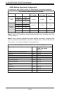
Memory Population for Optimal Performance
-For a Motherboard with One CPU (CPU1) Installed
# DIMMS CPU Channel 1 Channel 2 Channel 3 Channel 4
4 DIMMs CPU1 P1-1A P1-2A P1-3A P1-4A
8 DIMMs CPU1 P1-1A P1-1B P1-2A P1-2B P1-3A P1-3B P1-4A P1-4B
Memory Population for Optimal Performance
-For a Motherboard with Two CPUs (CPU1 & CPU2) Installed
# DIMMS CPU Channel 1 Channel 2 Channel 3 Channel 4
8 DIMMs
CPU1 P1-1A P1-2A P1-3A P1-4A
CPU2 P2-1A P2-2A P2-3A P2-4A
16 DIMMs
CPU1 P1-1A P1-1B P1-2A P1-2B P1-3A P1-3B P1-4A P1-4B
CPU2 P2-1A P2-1B P2-2A P2-2B P2-3A P2-3B P2-4A P2-4B
Memory Population for Optimal Performance – For a Motherboard with
Four CPUs (CPU1, CPU2, CPU3 & CPU4) Installed
# DIMMS CPU Channel 1 Channel 2 Channel 3 Channel 4
16 DIMMs
CPU1 P1-1A P1-2A P1-3A P1-4A
CPU2 P2-1A P2-2A P2-3A P2-4A
CPU3 P3-1A P3-2A P3-3A P3-4A
CPU4 P4-1A P4-2A P4-3A P4-4A
32 DIMMs
CPU1 P1-1A P1-1B P1-2A P1-2B P1-3A P1-3B P1-4A P1-4B
CPU2 P2-1A P2-1B P2-2A P2-2B P2-3A P2-3B P2-4A P2-4B
CPU3 P3-1A P3-1B P3-2A P3-2B P3-3A P3-3B P3-4A P3-4B
CPU4 P4-1A P4-1B P4-2A P4-2B P4-3A P4-3B P4-4A P4-4B