


6-2
A+ SERVER 2042G-TRF/6RF User's Manual
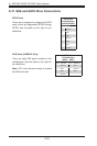
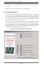
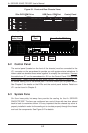
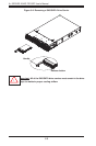
Figure 6-1. Front and Rear Chassis Views
6-2 Control Panel
The control panel (located on the front of the chassis) must be connected to the
JF1 connector on the serverboard to provide you with system status indications. A
ribbon cable has bundled these wires together to simplify the connection. Connect
the cable from JF1 on the serverboard to JP4 on the Control Panel PCB (printed
circuit board). Make sure the red wire plugs into pin 1 on both JF1 and JP4. Pull
all excess cabling out of the airfl ow path. The LEDs inform you of system status.
See Chapter 3 for details on the LEDs and the control panel buttons. Details on
JF1 can be found in Chapter 5.
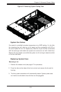
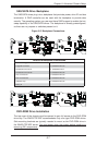
6-3 System Fans
Six 8-cm heavy-duty hot-swap fans provide the cooling for the A+ SERVER
2042G-TRF/6RF. The fans are confi gured as a set of three with two fans placed
back to back to maximize airfl ow. It is very important that the chassis top cover is
properly installed in order for the cooling air to circulate properly through the chassis
and cool the components. See Figure 6-2 for details.
Control PanelSlim DVD-ROM Drive
Power Supplies (2) SAS/SATA Drives (6)
Keyboard/
Mouse Ports
4 Low-Profi le PCI Slots
Ethernet
Ports
USB
Ports
COM1
Port
VGA
Port
USB Ports COM Port
IPMI LAN
Port