


6-4
A+ SERVER 2042G-TRF/6RF User's Manual
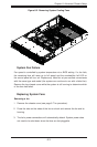
Installing a new fan
Replace the failed fan with an identical 8-cm, 12 volt fan (available from 1.
Supermicro, p/n FAN-0099L4).
Position the new fan into the space vacated by the failed fan previously 2.
removed. A "click" can be heard when the fan is fully installed in place and
the power connections are made.
If the system power is on, the hot-plug feature will cause the fan to start 3.
immediately upon being connected to its header on the serverboard.
Replace the chassis cover.4.
6-4 Drive Bay Installation/Removal
Accessing the Drive Bays
SAS/SATA Drives: You do not need to access the inside of the chassis or remove
power to replace or swap SAS/SATA drives. Proceed to the next step for instructions.
Note: You must use standard 1" high, SAS/SATA drives in the A+ SERVER
2042G-TRF/6RF.
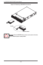
DVD-ROM: For installing/removing the DVD-ROM drive, you will need to gain
access to the inside of the server by removing the top cover of the chassis. Proceed
to the "DVD-ROM Installation" section later in this chapter for instructions.
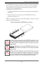
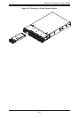
SAS/SATA Drive Installation
The SAS/SATA drives are mounted in drive carriers to simplify their installation
and removal from the chassis. These carriers also help promote proper airfl ow for
the drives. For this reason, even empty carriers without SAS/SATA drives installed
must remain in the chassis.
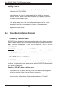
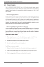
Mounting a SAS/SATA drive in a drive carrier
Install a drive into the carrier with the printed circuit board side facing down 1.
so that the mounting holes align with those in the carrier.
Secure the drive to the carrier with six screws, as shown in Figure 6-3.2.