


5-18
SUPERSERVER 5016T-TB User's Manual
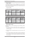
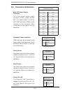
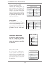
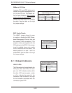
Universal Serial Bus (USB)
There are two Universal Serial Bus
ports located on the I/O panel. An
additional six USB headers are in-
cluded on the board, which may be
used for front side access (cables not
included). USB 6 and USB 7 are "Type
A" connectors. See the table on the
right for pin defi nitions.
Universal Serial Bus
Pin Defi nitions (USB)
USB0/1
Pin # Defi nition
USB4/5/6/7
Pin # Defi nition
1 +5V 1 +5V
2 PO- 2 PO-
3 PO+ 3 PO+
4 Ground 4 Ground
5 N/A 5 Key
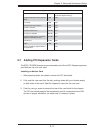
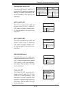
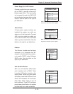
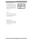
SGPIO Headers
The SGPIO (Serial General Purpose
Input/Output) headers are used to
communicate with an enclosure man-
agement chip on the backplane. See
the table on the right for pin defi ni-
tions.
SGPIO Header
Pin Defi nitions (T-SGPIO-0/T-TGPIO-1)
Pin# Defi nition Pin Defi nition
1NC 2 NC
3 Ground 4 DATA Out
5 Load 6 Ground
7 Clock 8 NC
NC = No Connection
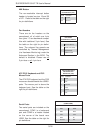
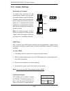
Power Supply SMBus Header
A Power SMB header is located at
SMB_PS1. Connect the appropriate
cable here to utilize SMB on your
system. See the table on the right for
pin defi nitions.
Power Supply SMB
Header Pin Defi nitions
(SMB_PS1)
Pin# Defi nition
1 Clock
2 Data
3 PWR Fail
4 Ground
5 +3.3V
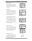
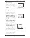
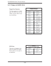
Onboard Power LED
An onboard Power LED header is
located at JLED. This header con-
nects to the control panel header
(JF1) to indicate the status of system
power. See the table on the right for
pin defi nitions.
Onboard PWR LED
Pin Defi nitions (JLED)
Pin# Defi nition
1 VCC
2 No Connection
3 Connection to PWR
LED in JF1