


Chapter 5: Advanced Serverboard Setup
5-19
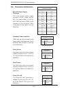
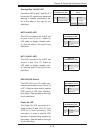
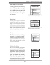
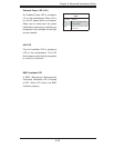
Alarm Reset
If three power supply modules are
installed, the system can notify you
when any of the three fails. Connect
JAR to a micro-switch to enable you
to turn off the alarm that is activated
when a power module fails. See the
table on the right for pin defi nitions.
Alarm Reset
Pin Defi nitions (JAR)
Pin Setting Defi nition
Pin 1 Ground
Pin 2 Alarm Reset
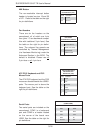
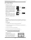
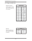
I-Button
The I-Button, located near the fl oppy
connector, is a computer chip en-
closed in a durable stainless contain-
er to enable RAID 5 under Software
RAID mode. See the table on the
right for pin defi nitions.
I-Button
Pin Defi nitions
Pin# Defi nition
1 Ground
2 GPIO1
3 Ground
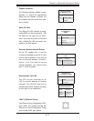
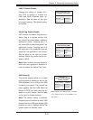
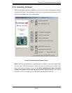
Power Supply Fail LED Header
Connect a cable from your power sup-
ply to JPWF to provide a warning of
power supply failure. This warning sig-
nal is passed through the PWR_LED
pin to indicate of a power failure on the
chassis. See the table on the right for
pin defi nitions.
Note: This feature is only available when using
Supermicro redundant power supplies.
Note: This feature is only available when using
Supermicro redundant power supplies.
PWR Supply Fail LED
Pin Defi nitions (JPWF)
Pin# Defi nition
1 PWR 1: Fail
2 PWR 2: Fail
3 PWR 3: Fail
4 Signal: Alarm Reset
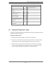
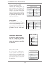
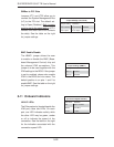
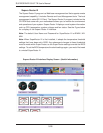
UID Button
Pin# Defi nition
1 Ground
2 Ground
3 Button In
4 Ground
Unit Identifi er Button
SW1 is a Unit Identifi er (UID) button
and is located next to FAN6. There
is another UID button located on the
control panel. When you push either
UID button, both Rear UID and Front
Panel UID Indicators will illuminate.
Push either button again to turn off
both indicators. These UID indicators
provide easy identifi cation of a system
unit that may be in need of service.