


6-2
SUPERSERVER 6015TC-T/6015TC-10G User's Manual
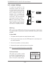
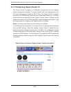
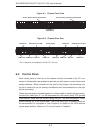
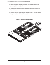
Figure 6-2. Chassis Rear View
6-2 Control Panel
Each control panel on the front of the chassis must be connected to the JF1 con-
nector on its assiciated serverboard to provide you with system control buttons and
status indicators. (When viewed from the front of the chassis, the serverboard on
the left is referred to as the primary serverboard and the serverboard on the right
as the secondary.)
These wires have been bundled together in a ribbon cable to simplify the connection.
Connect the cable from JF1 on the serverboard to the control panel PCB (printed
circuit board). Make sure the red wire plugs into pin 1 on both connectors. Pull all
excess cabling out of the airfl ow path. The LEDs inform you of system status for
the serverboard it is connected to. See Chapter 3 for details on the LEDs and the
control panel buttons. Details on JF1 can be found in Chapter 5.
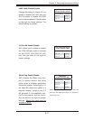
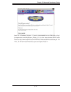
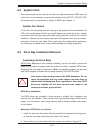
Figure 6-1. Chassis Front View
USB Ports COM Port VGA Port
LAN Ports LAN PortsPower Supply
PCI-Express x16 Slot PCI-Express x16 Slot
SATA Drives
Control Panel: Primary Serverboard Control Panel: Secondary Serverboard
10 Gb Port*
USB Ports COM Port VGA Port
10 Gb Port*
*The 10 Gb ports are included on the 6015TC-10G only.