


Chapter 7: BIOS
7-11
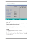
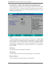
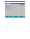
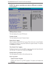
XAdvanced Chipset Control
Access the submenu to make changes to the following settings.
Warning: Take Caution when changing the Advanced settings. An incorrect
setup, a very high DRAM frequency or an incorrect DRAM timing may cause
the system become unstable. When this occurs, reset the setting to the default
setting.
Clock Spectrum Feature
If Enabled, the BIOS will monitor the level of Electromagnetic Interference caused
by the components and will attempt to decrease the interference whenever needed.
The options are Enabled and Disabled.
Crystal Beach Features
This feature cooperates with the Intel I/O AT (Acceleration Technology) to accelerate
the performance of TOE devices. (Note: A TOE device is a specialized, dedicated
processor that is installed on an add-on card or a network card to handle some or
all packet processing of this add-on card. For this motherboard, the TOE device is
built inside the South Bridge chip.) The options are Enabled and Disabled.
SERR Signal Condition
This setting specifi es the ECC Error conditions that an SERR# is to be asserted.
The options are None, Single Bit, Multiple Bit and Both.
4GB PCI Hole Granularity
This feature allows you to select the granularity of PCI hole for PCI slots. If MTRRs
are not enough, this option may be used to reduce MTRR occupation. The options
are 256 MB, 512 MB, 1GB and 2GB.
Channel 0 Rank Sparing/Channel 1 Rank Sparing
Select Enable to enable the function of memory sparing for Memory Bus Branch 0
or Branch 1. The options are Enabled and Disabled.
Enhanced x8 Detection
Select Enabled to enable Enhanced x8 DRAM UC Error Detection. The options
are Disabled and Enabled.