


2-5
Chapter 2: Technical Specifi cations and Installation
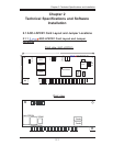
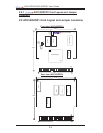
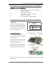
2.2.2 Connector and Header Descriptions (*AOC-SOZCR1)
Connector Description
J1 Systerm Management Bus (I
2
C) (*See Page 2-2 for
I
2
C cable connection.)
J2 SCSI Mode (On: Enable)
J3 Serial ATA (SATA2) Mode (On: Enable)
J4 SAS Mode (On: Enable)
J6 Flash Firmware (On: Flashing Firmware.)
*Note 1: Refer to the layout on Page 2-4 for the locations of the Connectors and
LED Indicators.
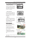
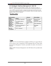
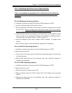
SMB (I
2
C)
A System Management Bus header is
located at J1. Connect the I
2
C cable
here to utilize SMB on your add-on
card (*See below). See the table on
the right for pin defi nitions.
SMB (I
2
C)
Pin Definitions (J1)
Pin
Number
1
2
3
Definition
Data
Ground
Clock
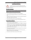
2.2.3 SMB Connector and Pin Defi nitions (*AOC-SOZCR1)
I
2
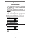
C cable Connection
1. The I
2
C Cable has a 3-pin connec-
tor on one end, and a 4-pin connector
on the other end.
2. Connect the 3-pin connector of the
cable to the 3-pin I
2
C Connector (J1)
on the AOC-SOZCR1 card.
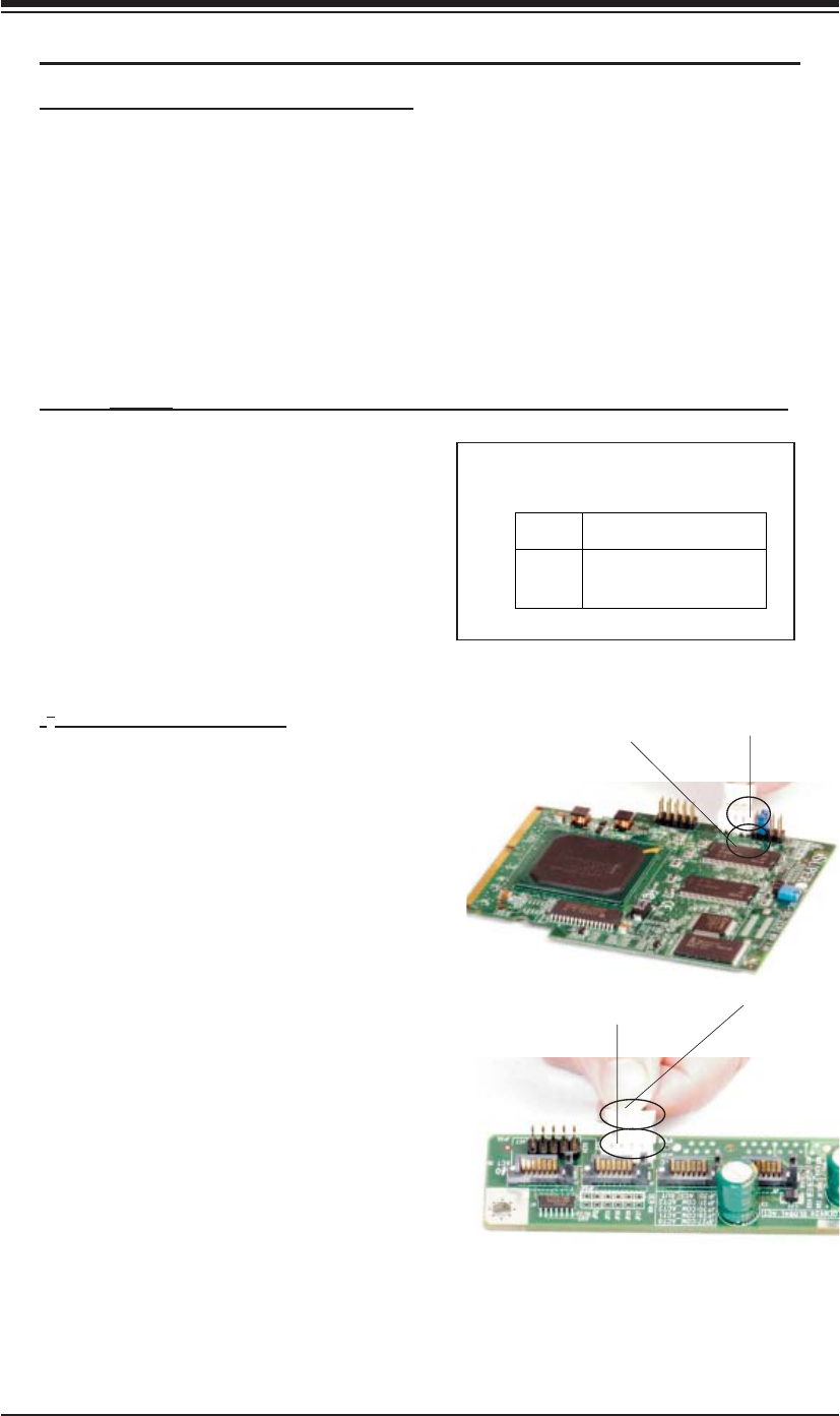
3. Connect the 4-pin connector of the
cable to the 4-pin I
2
C Connector on
the backplane as shown on the right.
3-PinConnector on
the cable
3-Pin Connector (J1) on
the SOZCR1
4-Pin I
2
C Connector
on the Backplane
4-Pin Connector on
the cable