


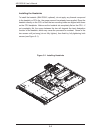
5-12
AS1020S-8 User's Manual
5-9 Connector Defi nitions
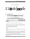
Required Connection
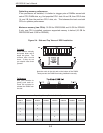
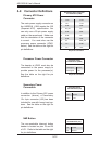
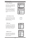
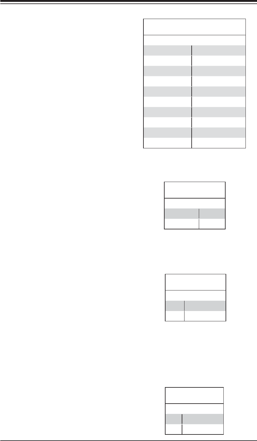
ATX Power 20-pin Connector
Pin Defi nitions (J1B4)
Pin# Defi nition Pin # Defi nition
11 +3.3V 1 +3.3V
12 -12V 2 +3.3V
13 COM 3 COM
14 PS_ON 4 +5V
15 COM 5 COM
16 COM 6 +5V
17 COM 7 COM
18 -5V 8 PWR_OK
19 +5V 9 5VSB
20 +5V 10 +12V
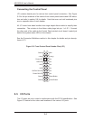
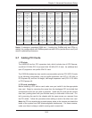
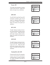
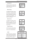
NMI Button
The non-maskable interrupt button
header is located on pins 19 and 20
of JF1. Refer to the table on the right
for pin defi nitions.
NMI Button
Pin Defi nitions (JF1)
Pin# Defi nition
19 Control
20 Ground
Required Connection
Primary ATX Power
Connector
The main power supply connector on
the H8DSR-8 (J1B4) meets the SSI
(Superset ATX) specification. You
can only use a 20-pin power supply
cable on the serverboard. Make sure
that the orientation of the connector
is correct. You must also use the
processor power connector (JPW2,
below.) See the table on the right for
pin defi nitions.
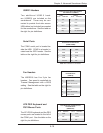
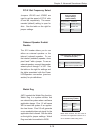
Secondary Power
Connection
In addition to the Primary ATX power
connector (above), a Secondary
12v 4-pin connector (J32) has been
included for use with heavy-load sys-
tems. See the table on the right for
pin defi nitions.
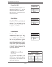
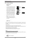
Processor Power
Pin Defi nitions (JPW2)
Pins Defi nition
1 through 4 Ground
5 through 8 +12V
Secondary Power
Pin Defi nitions (J32)
Pins Defi nition
1 & 2 Ground
3 & 4 +12V
Processor Power Connector
The header at JPW2 must also be
connected to the power supply to
provide power for the processor(s).
See the table on the right for pin
defi nitions.