


5-22
AS1020S-8 User's Manual
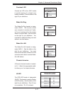
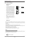
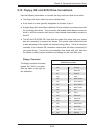
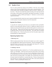
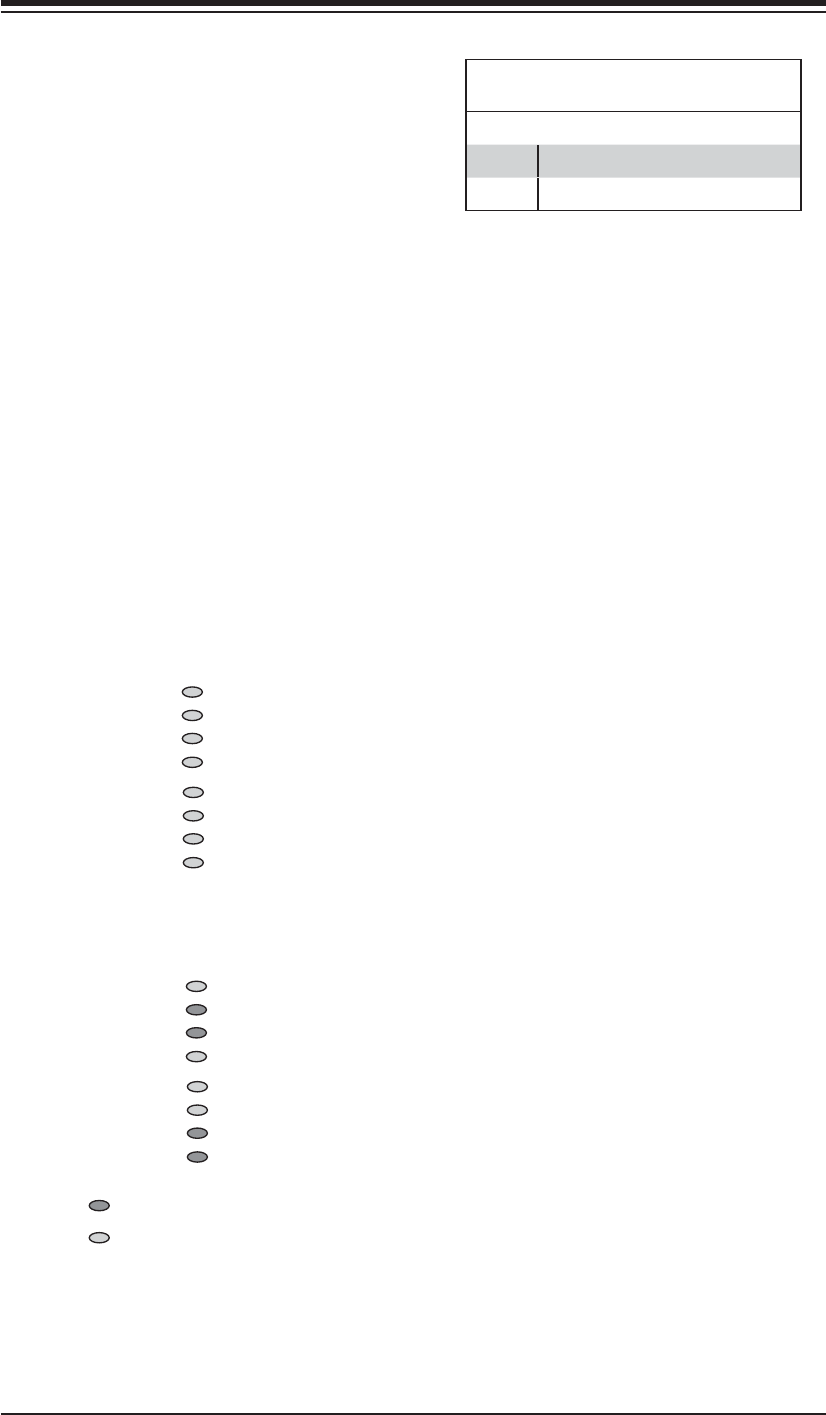
Reading the POST Code LEDs:
When on, each of the eight separate LEDs
represent the value of the number shown
beside it in the diagram on the left. Add up
the numerical values of each illuminated
LED in the DB5-DB8 column to get the high
(left) digit and those in the DB1-DB4 column
to get the low (right) digit of the correspond-
ing POST code.
Example:
The example on the left indicates a hexa-
decimal POST code of C6. This is deter-
mined in the following manner:
DB1-DB4 (low digit): 4 + 2 = 6
DB5-DB8 (high digit): 8 + 4 = 12
(decimal 12 = hexidecimal C)
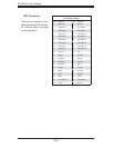
Decimal Hexidecimal Equivalent
0-9 0-9
10 A
11 B
12 C
13 D
14 E
15 F
1
2
4
8
DB5-8
DB1-4
1
2
4
8
1
2
4
8
DB5-8
DB1-4
1
2
4
8
Example:
= Unilluminated LED (0)
= Illuminated LED (1)
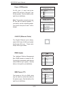
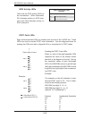
POST Code LEDs
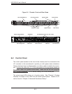
Eight surface-mounted LEDs are located near one end of the 1UIPMI slot. These
LEDs are used to provide POST code information. See the diagrams below for
reading the LEDs and refer to Appendix B for a complete list of POST codes.
Toward edge of board
↑
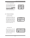
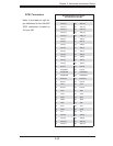
SCSI Activity LEDs
There are two SCSI activity LEDs on
the serverboard. When illuminated,
DA1 indicates activity on SCSI chan-
nel A and DA2 indicates activity on
SCSI channel B.
SCSI Channel Activity LEDs
(DA1/DA2)
State System Status
On SCSI Channel Active
Off SCSI Channel Inactive