


5-16
AS1020S-8 User's Manual
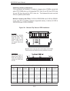
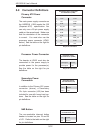
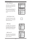
Power LED/Speaker
On JD1, pins 1, 2, and 3 are for the
power LED and pins 4 through 7 are
for the speaker. See the tables on the
right for pin defi nitions.
Note: The speaker connector pins are
for use with an external speaker. If
you wish to use the onboard speaker,
you should close pins 6 and 7 with a
jumper.
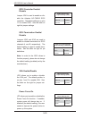
Speaker Connector
Pin Defi nitions (JD1)
Pin# Defi nition
4 Red wire, Speaker data
5 No connection
6 Buzzer signal
7 Speaker data
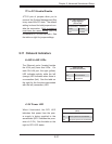
PWR LED Connector
Pin Defi nitions (JD1)
Pin# Defi nition
1 +Vcc
2 -Vcc
3 -Vcc
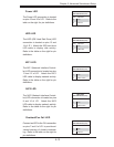
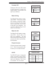
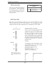
IPMB Header
The Intelligent Platform Management
Bus (IPMB) header is located at J22.
Connect the appropriate cable here to
utilize IPMB on your system. See the
table on the right for pin defi nitions.
IPMB
Pin Defi nitions (J22)
Pin# Defi nition
1 Data
2 Ground
3 Clock
4N/A
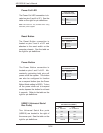
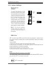
JLAN1/2 (Ethernet Ports)
Two Gigabit Ethernet ports (desig-
nated JLAN1 and JLAN2) are located
beside the VGA port. These ports
accept RJ45 type cables.
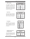
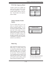
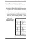
SMB Power (I
2
C)
The header at J24 is for SMB, which
may be used to monitor the status of
the power supply. See the table on the
right for pin defi nitions.
SMB Power (I
2
C)
Pin Defi nitions (J24)
Pin# Defi nition
1 Clock
2 SMB Data
3N/A
4N/A
5N/A