


Chapter 5: Advanced Serverboard Setup
5-17
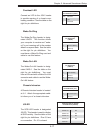
Wake-On-Ring
The Wake-On-Ring header is desig-
nated JWOR. This function allows
your computer to receive and "wake-
up" by an incoming call to the modem
when in suspend state. See the table
on the right for pin defi nitions. You
must have a Wake-On-Ring card and
cable to use this feature.
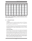
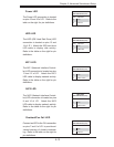
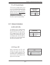
Wake-On-Ring
Pin Defi nitions
(JWOR)
Pin# Defi nition
1 Ground (Black)
2 Wake-up
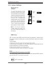
Wake-On-LAN
The Wake-On-LAN header is desig-
nated JWOL1. See the table on the
right for pin defi nitions. You must
have a LAN card with a Wake-On-LAN
connector and cable to use the Wake-
On-LAN feature.
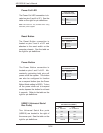
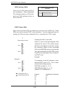
Wake-On-LAN
Pin Defi nitions
(JWOL1)
Pin# Defi nition
1 +5V Standby
2 Ground
3 Wake-up
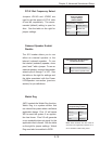
Overheat LED
Connect an LED to the JOH1 header
to provide warning of a chassis over-
heating condition. See the table on the
right for pin defi nitions.
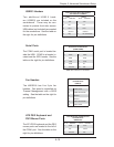
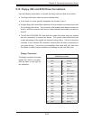
Overheat LED
Pin Defi nitions (JOH1)
Pin# Defi nition
1 +5V
2 OH Active
Chassis Intrusion
A Chassis Intrusion header is located
at JL1. Attach the appropriate cable
to inform you of a chassis intrusion.
Chassis Intrusion
Pin Defi nitions (JL1)
Pin# Defi nition
1 Intrusion Input
2 Ground
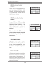
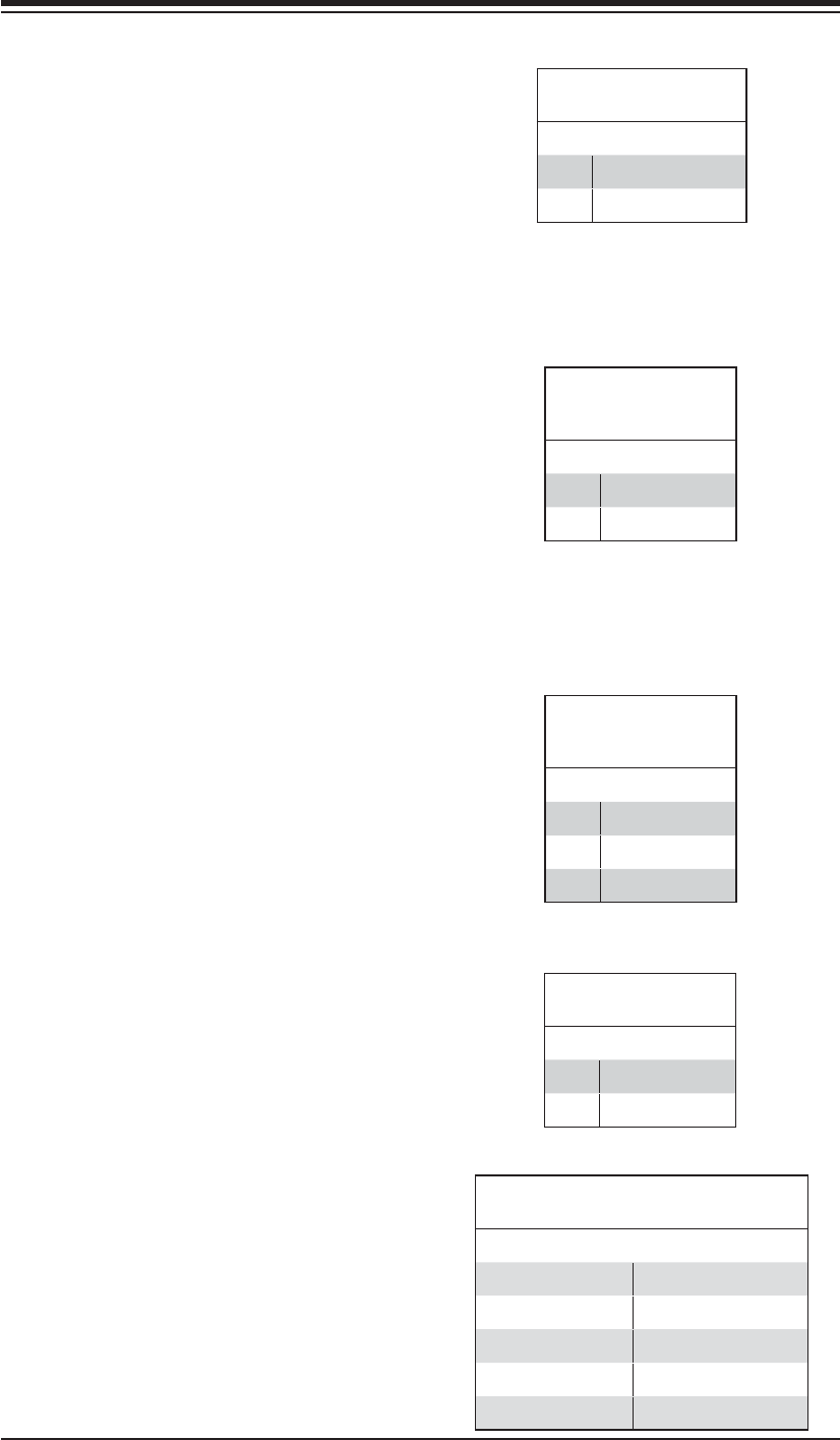
JSLED
The SCSI LED header is designated
JSLED. This header is used to display
all SATA activity. See the table on the
right for pin defi nitions. Pins 6-9 are
no connection. Pin 10 is absent.
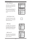
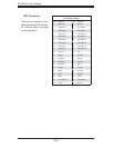
SCSI LED Activity Header
Pin Defi nitions (JSLED)
Pin# Defi nition Pin# Defi nition
1 SATA0 Act. 6 NC
2 SATA1 Act. 7 NC
3 SATA2 Act. 8 NC
4 SATA3 Act. 9 NC
5 Common