Chapter 1: Introduction
1-5
Cooling System
The SC813TQ+-500 chassis' revolutionary cooling design has been optimized to
provide suffi cient cooling for dual processor confi gurations. The chassis includes
four counter-rotating 4-cm fans located in the middle of the chassis. In the event
of a fan failure, the ambient air temperature inside the chassis will rise and activate
an overheat LED (fan speed is controlled by the system temperature).
A fan speed control setting in BIOS allows chassis fan speed to be determined by
system temperature [recommended setting is 3-pin (Server)].
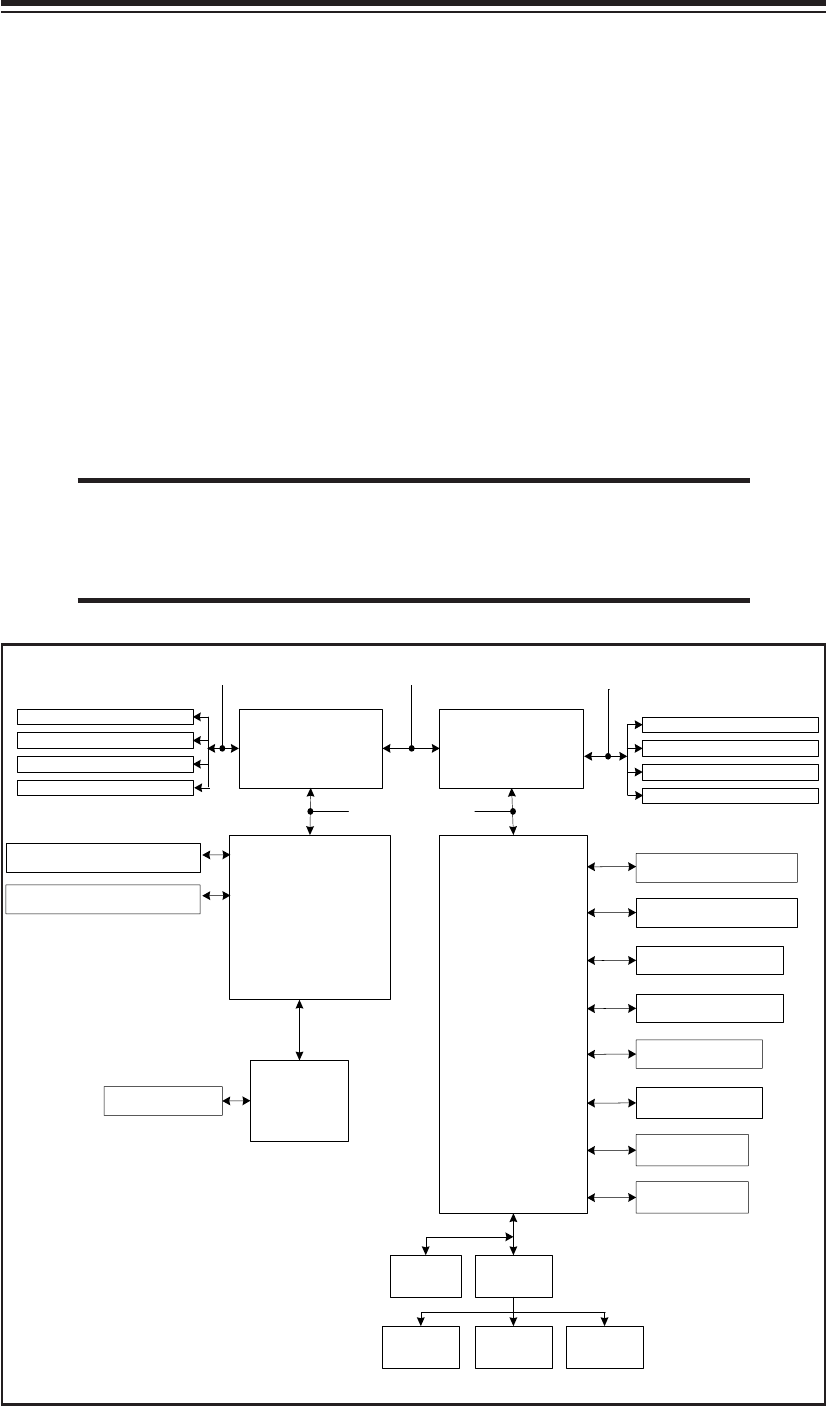
Figure 1-1. nVidia nForce Pro 2200/AMD-8132 Chipset:
System Block Diagram
Note: This is a general block diagram and may not exactly represent
the features on your serverboard. See the previous pages for the
actual specifi cations of your serverboard.
nVidia
nForce Pro
2200
AMD Opteron
TM
Processor (CPU2)
16 x 16 HT link (1 GHz)
DIMM 1B
DIMM 2B
DIMM 3B
DIMM 4B
DIMM 1A
DIMM 2A
DIMM 3A
DIMM 4A
128-bit data + 16-bit ECC
DDR400/333/266
DDR400/333/266
16 x 16 HT link (1 GHz)
BCM5721 (LAN1)
SATA Ports (4)
IDE (ATA133)
USB Ports (4)
S I/OBIOS
Kybd/
Mouse
Floppy
COM
Ports
AMD Opteron
TM
Processor (CPU1)
128-bit data + 16-bit ECC
AMD-8132
PCI-X 133 (Slot 6)
PCI-X 100 (Slot 7): ZCR
CH B
CH A
AIC-9410WSAS Ports (8)
LPC
PCI Express x8 Slot
PCI Express x8 Slot
BCM5721 (LAN2)
ATI Rage XL


