


Chapter 5: Advanced Serverboard Setup
5-23
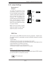
5-11 Onboard Indicators
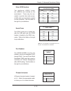
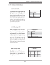
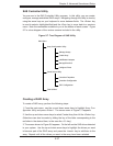
LAN1/LAN2 LEDs
The Ethernet ports (located beside the
VGA port) have two LEDs. On each
Gb LAN port, the right LED (when
facing the port) indicates activity while
the left LED may be green, orange or
off to indicate the speed of the con-
nection. See the table on the right for
the functions associated with the left
(connection speed) LED.
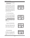
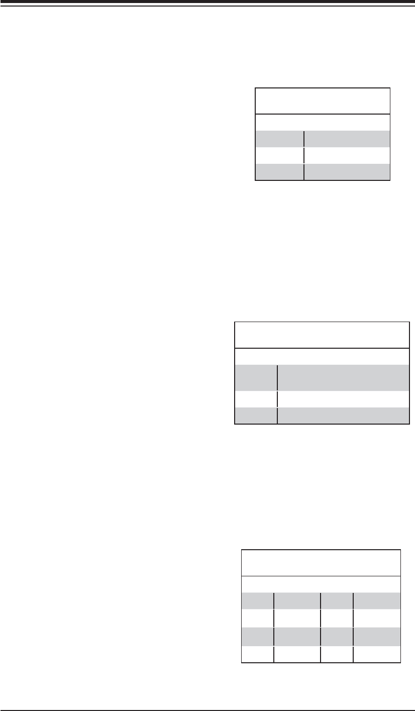
LAN1/2: Left LED
(Connection Speed Indicator)
LED Color Defi nition
Off 10 MHz
Green 100 MHz
Amber 1 GHz
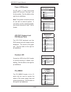
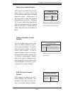
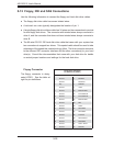
+3.3V Standby LED
When illuminated, the DP1 LED indi-
cates that +3.3V standby power from
the power supply is being supplied to
the serverboard. DP1 should normally
be illuminated when the system is con-
nected to AC power, whether turned
on or not. DP1 will fl ash on and off
when the system is in an S1, S3
(Suspend to RAM) or S4 (Suspend to
Disk) state.See the table on the right
for DP1 LED states.
+3.3V Standby LED
(DP1)
State System Status
On Standby power present on
serverboard
Off No power connected
Flashing System in standby state
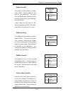
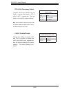
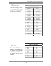
SAS Activity LEDs
The SAS Activity LED indicators
(DS1-DS8) indicate the activity status
of SAS ports (0-7). See the table on
the right for pin defi nitions.
SAS Activity LEDs
(DS1-DS8)
DS# Defi nition DS# Defi nition
DS1 SAS0:Act DS5 SAS4:Act
DS2 SAS1:Act DS6 SAS5:Act
DS3 SAS2:Act DS7 SAS6:Act
DS4 SAS3:Act DS8 SAS7:Act