


5-18
AS1020C-3 User's Manual
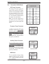
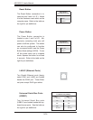
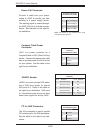
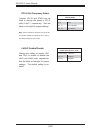
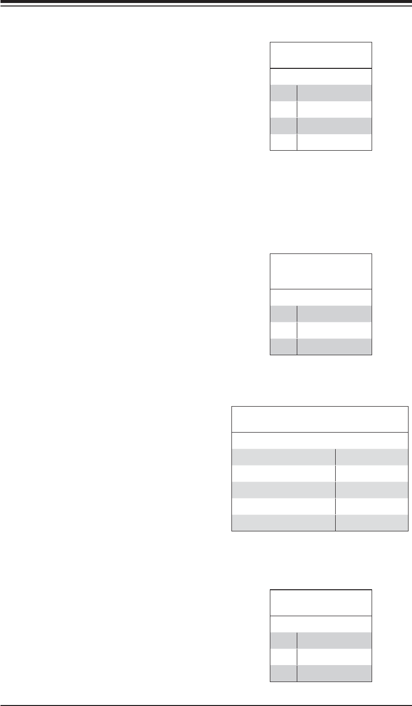
Power Fail Connector
Connect a cable from your power
supply to JPWF to provide you with
warning of a power supply failure.
The warning signal is passed through
the PWR_LED pin to indicate a power
failure. See the table on the right for
pin defi nitions.
Power Fail Connector
Pin Defi nitions (JPWF)
Pin# Defi nition
1 P/S 1 Fail Signal
2 P/S 2 Fail Signal
3 P/S 3 Fail Signal
4 Reset (from MB)
Note: This feature is only available when using
redundant power supplies.
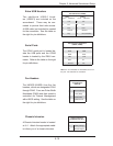
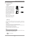
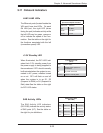
Compact Flash Power
Connector
JWF1 is a power connector for a
Compact Flash or DOC (Disk-On-Chip)
device. Connect the appropriate cable
here to provide power to such a device
on your system. See the table on the
right for pin defi nitions.
Compact Flash Power
Connector
Pin Defi nitions (JWF1)
Pin# Defi nition
1+5V
2 Ground
3 Signal
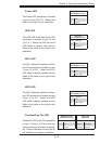
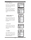
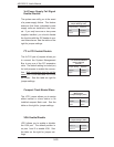
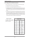
JSLED1 Header
JSLED1 is used to provide LED indica-
tion of SAS drive activity for internal
SAS ports 0-3. Refer to the table on
the right for pin defi nitions. SAS ports
4-7 are external ports and do not have
board level support for activity LEDs.
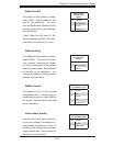
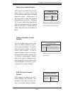
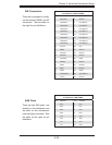
I
2
C for SAS Connector
The JS4 connection is used to provide
I2C monitoring for the SAS backplane.
See the table on the right for pin defi -
nitions.
Note: NC indicates no connection.
JSLED1 Header Pin Defi nitions
(JSLED1)
Pin # Defi nition Pin # Defi nition
1 SAS Port0 Active 6 NC
2 SAS Port1 Active 7 NC
3 SAS Port2 Active 8 NC
4 SAS Port3 Active 9 NC
5 SAS Port0-3 Signal 10 No pin
I
2
C for SAS Connector
Pin Defi nitions (JS4)
Pin# Defi nition
1I
2
C Data
2I
2
C Clock
3 Ground