


2-10
C2SEA/C2SEE User's Manual
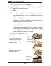
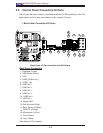
JL1
JI2C1
JI2C2
JOH1
JPUSB1
JPI1
JWD1
JPL1
JPAC
JLED1
JPD1
COM1
JPW1
Floopy
JPW2
JWOL1
SMBUS_PS1
DIMM1
DIMM2
CD1
JBT1
SPKR1
LE1
JD1
Fan5
Fan4
Fan1
Fan3
Fan2
LAN1
JPUSB2
DIMM2B
DIMM4
DIMM3
USB 10/11
USB 8/9
USB6
1394_2
Slot7 PCI-E x1
Slot6 PCI-E Gen2 x16
Slot3 PCI 33MHz
HD AUDIO
JWOR
CPU
CPU Fan
FP Audio
1394_1
CMOS CLEAR
C2SEA/C2SEE
IDE
VGA
HDMI
USB/0/1
I-SATA3
I-SATA2
I-SATA1
I-SATA0
Slot1 PCI 33MHz
Slot5 PCI 33MHZ
Slot4 PCI-E x4 on x16
KB/MOUSE
SPI BIOS
Slot2 PCI 33MHz
DIMM2A
DIMM1B
DIMM1A
USB7
JF1
USB2/3/4/5
SPDIF_Out
Printer
I-SATA4
I-SATA5
Battery
Intel
G45 (C2SEA)
G43 (C2SEE)
ICH10
Intel
Lan
CTRL
S I/O
IDE
CTRL
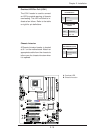
Power Button
OH/Fan Fail LED
1
NIC1 LED
Reset Button
2
HDD LED
Power LED
LED_Anode+
LED_Anode+
LED_Anode+
LED_Anode+
Ground
Ground
X
X
LED_Anode
+
1516
X
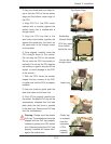
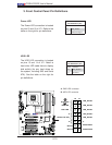
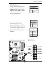
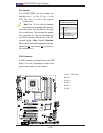
Power LED
The Power LED connection is located
on pins 15 and 16 of JF1. Refer to the
table on the right for pin defi nitions.
Power LED
Pin Defi nitions (JF1)
Pin# Defi nition
15 LED_Anode+
16 PWR LED Signal
3. Front Control Panel Pin Defi nitions
A. PWR LED connector
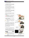
B. HDD LED connector
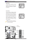
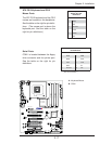
HDD LED
The HDD LED connection is located
on pins 13 and 14 of JF1. Attach a
hard drive LED cable here to display
disk activity (for any hard drives on
the system, including SAS and Serial
ATA). See the table on the right for
pin defi nitions.
HDD LED
Pin Defi nitions (JF1)
Pin# Defi nition
13 LED_Anode+
14 HD Active
A
B