


Chapter 2: Installation
2-13
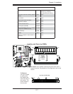
JL1
JI2C1
JI2C2
JOH1
JPUSB1
JPI1
JWD1
JPL1
JPAC
JLED1
JPD1
COM1
JPW1
Floopy
JPW2
JWOL1
SMBUS_PS1
DIMM1
DIMM2
CD1
JBT1
SPKR1
LE1
JD1
Fan5
Fan4
Fan1
Fan3
Fan2
LAN1
JPUSB2
DIMM2B
DIMM4
DIMM3
USB 10/11
USB 8/9
USB6
1394_2
Slot7 PCI-E x1
Slot6 PCI-E Gen2 x16
Slot3 PCI 33MHz
HD AUDIO
JWOR
CPU
CPU Fan
FP Audio
1394_1
CMOS CLEAR
C2SEA/C2SEE
IDE
VGA
HDMI
USB/0/1
I-SATA3
I-SATA2
I-SATA1
I-SATA0
Slot1 PCI 33MHz
Slot5 PCI 33MHZ
Slot4 PCI-E x4 on x16
KB/MOUSE
SPI BIOS
Slot2 PCI 33MHz
DIMM2A
DIMM1B
DIMM1A
USB7
JF1
USB2/3/4/5
SPDIF_Out
Printer
I-SATA4
I-SATA5
Battery
Intel
G45 (C2SEA)
G43 (C2SEE)
ICH10
Intel
Lan
CTRL
S I/O
IDE
CTRL
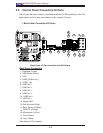
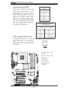
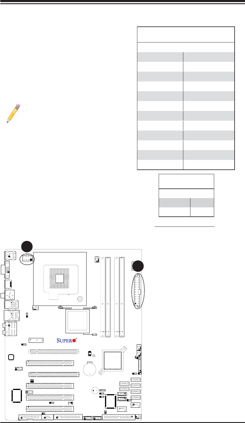
2-6 Connecting Cables
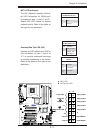
ATX/Auxiliary Power Connectors
A 24-pin main power connector is
located at JPW1, and a 8-pin power
connector is located at JPW2 on the
motherboard. These power connectors
meet the SSI EPS 12V specifi cation.
Note: The 8-pin 12V PWR sup-
ply is also required to provide
adequate power to the processor.
See the table on the right for pin
defi nitions.
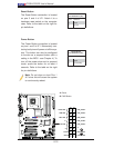
ATX Power 24-pin Connector
Pin Defi nitions
Pin# Defi nition Pin # Defi nition
13 +3.3V 1 +3.3V
14 -12V 2 +3.3V
15 COM 3 COM
16 PS_ON 4 +5V
17 COM 5 COM
18 COM 6 +5V
19 COM 7 COM
20 Res (NC) 8 PWR_OK
21 +5V 9 5VSB
22 +5V 10 +12V
23 +5V 11 +12V
24 COM 12 +3.3V
A. 24-pin ATX PWR
B. 8-pin PWR
A
B
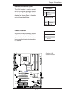
Required Connection
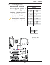
12V 8-pin CPU PWR
Pin Defi nitions
Pins Defi nition
1 through 4 Ground
5 through 8 +12V