


Chapter 2: Installation
2-27
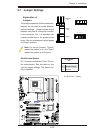
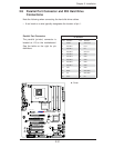
JL1
JI2C1
JI2C2
JOH1
JPUSB1
JPI1
JWD1
JPL1
JPAC
JLED1
JPD1
COM1
JPW1
Floopy
JPW2
JWOL1
SMBUS_PS1
DIMM1
DIMM2
CD1
JBT1
SPKR1
LE1
JD1
Fan5
Fan4
Fan1
Fan3
Fan2
LAN1
JPUSB2
DIMM2B
DIMM4
DIMM3
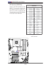
USB 10/11
USB 8/9
USB6
1394_2
Slot7 PCI-E x1
Slot6 PCI-E Gen2 x16
Slot3 PCI 33MHz
HD AUDIO
JWOR
CPU
CPU Fan
FP Audio
1394_1
CMOS CLEAR
C2SEA/C2SEE
IDE
VGA
HDMI
USB/0/1
I-SATA3
I-SATA2
I-SATA1
I-SATA0
Slot1 PCI 33MHz
Slot5 PCI 33MHZ
Slot4 PCI-E x4 on x16
KB/MOUSE
SPI BIOS
Slot2 PCI 33MHz
DIMM2A
DIMM1B
DIMM1A
USB7
JF1
USB2/3/4/5
SPDIF_Out
Printer
I-SATA4
I-SATA5
Battery
Intel
G45 (C2SEA)
G43 (C2SEE)
ICH10
Intel
Lan
CTRL
S I/O
IDE
CTRL
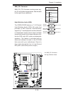
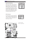
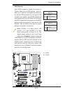
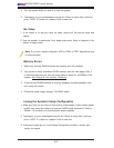
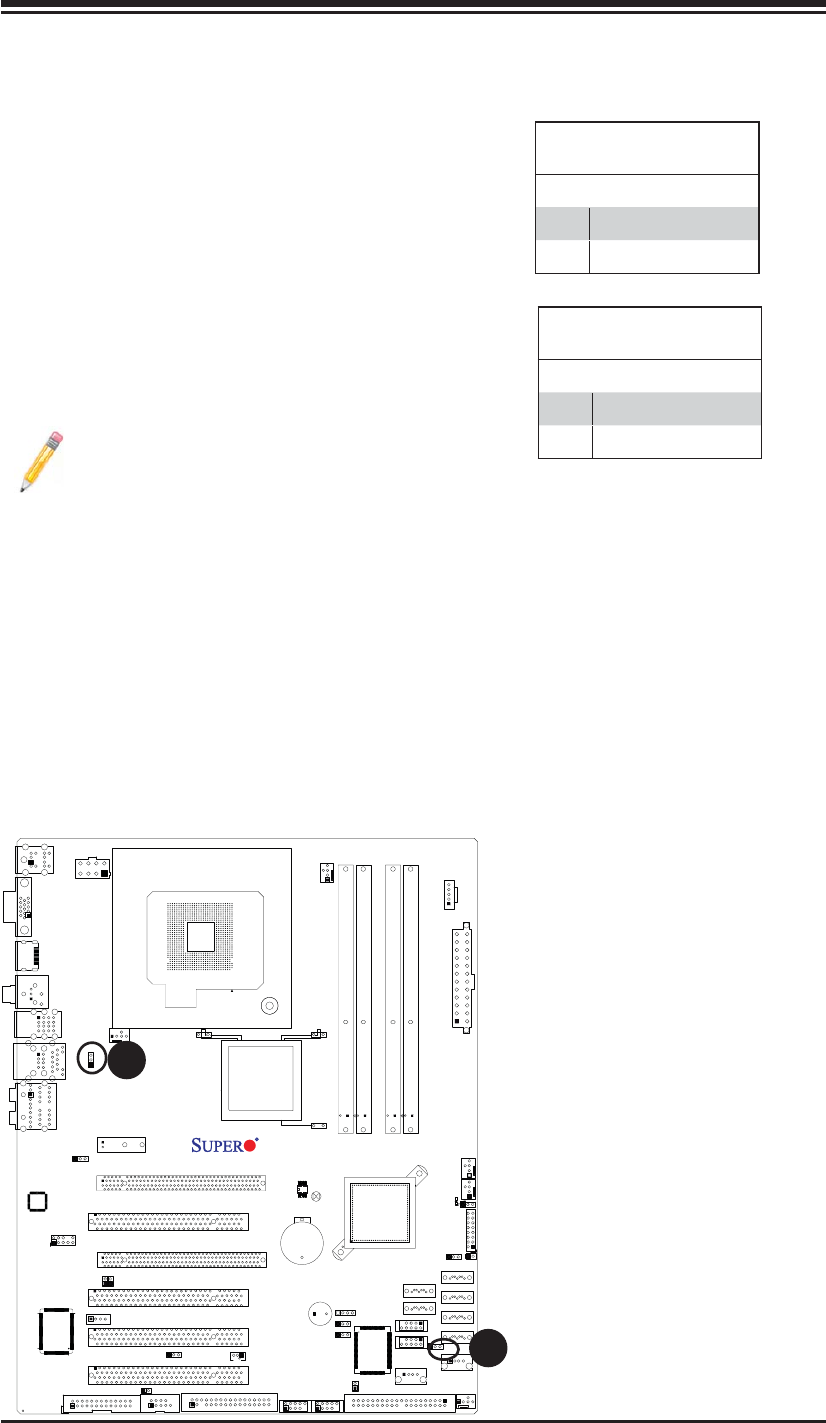
USB Wake-Up
Use JPUSB jumpers to enable the function of
"System Wake-Up via USB devices", which al-
lows you to "wake-up" the system by pressing a
key on the USB keyboard or by clicking the USB
mouse of your system. The JPUSB jumpers are
used together with the USB Wake-Up function in
the BIOS. Enable both the jumpers and the BIOS
setting to allow the system to "wake-up via USB
Devices". See the table on the right for jumper
settings and jumper connections.
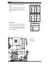
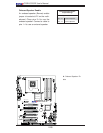
Note: JPUSB1 is for Back Panel USB
ports:0~1, 2~5, and JPUSB2 is for Front
Panel USB ports:6, 8~9 and 10~11.) The
default jumper setting for the Front Panel
USB ports is Disabled. However, when the
"USB Wake-Up" function is enabled in the BIOS,
and the desired USB ports are enabled via the
JPUSB jumper, please be sure to remove all
USB devices from the USB ports whose USB
jumpers are set to "Disabled" before the system
goes into the standby mode.
JPUSB1 (Back Panel USB
Wake-up)
Pin# Defi nition
1-2 Enabled (Default)
2-3 Disabled
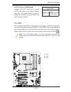
JPUSB2 (Front Panel USB
Wake-up)
Pin# Defi nition
1-2 Enabled
2-3 Disabled (default)
A. JPUSB1
B. JPUSB2
A
B