


1-4
Introduction
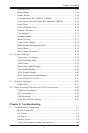
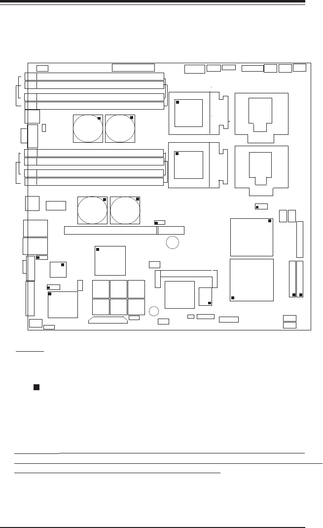
SUPER i2DMR-8G2/i2DMR-iG2 User's Manual
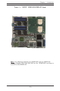
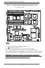
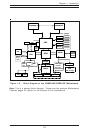
Figure 1-2. SUPER i2DMR-8G2/i2DMR-iG2 Motherboard Layout
(not drawn to scale)
24Pin PW1J20
J16
J15
J13
J14
1
5
2
6
USB0/1
WOR
J6
J5
COM1
J11
J9
J12
J10
3
7
4
8
LAN1
LAN2
JLAN2
JLAN1
VGA
J2
J3
JA1
SCSI A
J18
CN4
USB4/5
J21
SPKR
JBT1
J25
Chassis
Intrusion
J19
JV1
VGA
Enabled
J7
CLR
CMOS
S6
S5
S4
S3
S2 S1
IPMI
J4
SMB
CPU1
CPU2
J31
WD
Reset
Fan2
24-Pin PW2
IDE1
IDE2
Fan6
Fan5
Fan1
SMB
PW
J27
CN5
Alarm
Reset
DIMM1
DIMM2
DIMM5
DIMM6
DIMM3
DIMM7
DIMM4
DIMM8
MRH-D
MRH-D
MRH-D
MRH-D
PCI-X (256 Pin)
SCSI B
7902
SCSI
Controller
P64H
ICH4
SIOH
(South
Bridge)
(North
Bridge)
SNC
(VRM)
(VRM)(top)
ATI-RAGE
_XL(bottom)
Front Panel
CTLR
J35
J36
J37
GLAN
Enable
J26
Speaker
U62
1. Jumpers not noted are for testing purposes only.
SCSI
Enable
COM2
USB2/3
Fan7
J38
J1
82546
GLAN
CTLR
Fan8
S I/O
Fan4
Fan3
Notes:
2. " " indicates the location of Pin 1.
3. For 1U servers, please use Fan1 and Fan2 for CPU cooling.
For 2U servers, please use Fan1, Fan2, Fan3 & Fan4 for CPU cooling.
U66
J29
J30
J22
BIOS1
BIOS2
BIOS3
BIOS4BIOS5
BIOS6
4. The difference between the i2DMR-8G2 and the i2DMR-iG2: There is Adaptec
7902 Ultra 320 SCSI on the i2DMR-8G2, and there is no SCSI on the i2DMR-iG2.
Warning: The heatsink on the MRH-D chip has been pre-installed by the
manufacturer. Please do not touch it. Turning the heatsink in a wrong way will
damage it and will void the manufacturer's warranty.
PWR Pod
PW Pod
Battery
J34
ITP
Connector
J28
PWR
Fault
CN1
CN3
SCSI Ch.B
Termination
SCSI Ch.A
Termination