


Chapter 1: Introduction
1-5
Introduction
Jumper Description Default Setting
CN1, CN3 SCSI Cha.A(CN3)/Cha.B(CN1)Termination (*Note4)
Open (Enabled)
J7 GLAN Enable/Disable Pins 1-2 (Enabled)
J31 Watch Dog Pins 1-2 (Reset)
JBT1 CMOS Clear (*Note 4)
JA1 SCSI Enable/Disable (*Note5) Pins 1-2 (Enabled)
JV1 VGA Enable/Disable Pins 1-2 (Enabled)
Connector Description
Alarm Reset (CN5) Fail Alarm Reset Switch
BIOS#1-6 (S1-6) BIOS#1-6
Chassis Intrusion (J25) Chassis Intrusion Header
COM1 (J5), COM2 (J38)COM1 & COM2 Serial Port and Header
CPU1(J30), CPU2 (J29) CPU 1/2 Sockets
DIMM#1-#8 (J9-J16) Memory (RAM) Slots:DIMM1(J16),DIMM2 (J13),
DIMM3 (J11), DIMM4(J9), DIMM5 (J15),
DIMM6 (J14), DIMM7 (J12), DIMM8 (J10)(*Note 2)
Fan Headers (1-8) Fan1-Fan8 Headers.
Front Panel CTRL (U66)Front Control Panel Connector (*Note 3)
IDE1 (J37), IDE2 (J35) IDE1/2 Hard Disk Drive Connectors
IPMI (J26) IPMI 1.5, 2.0 Connector
ITP (J34) ITP Connector (For Testing Only)
PCI-X (J19) PCI-X Bus 256-Pin Slot
PWR1(J20), PWR2(J36) Power1 and Power2 24-Pin-Connectors
PWR Fault (U62) Power Fault Connector
Speaker (CN4) Speaker Connector(*Note3)
SMB (J22) System Management Bus Connector
SMB_Power (J27) System Management Bus Power Header
SCSI A&B (J18,J3) SCSI A Connector(J18), SCSI B Connector(J3)
(*Note 4)
USB 0/1(J1),USB2/3(J4)Back Panel Universal Serial Ports
USB4/5 (J21) Front Panel USB Headers
VGA Connector (J2) VGA Connector
WOR (J6) Wake-on-Ring Header
(*Notes: 1. For 1U servers, use Fan1&Fan2 for CPU cooling. For 2U
servers, use Fan1, Fan2, Fan3, Fan4 for CPU cooling.
2. See Chapter 2 for Memory Installation Instructions.
3. See Chapter 2 for detailed information.
4. For i2DMR-8G2 only)
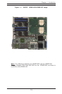
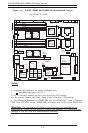
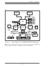
Quick Reference (i2DMR-8G2/i2DMR-iG2)
(*Please refer to Chapter 2 for pin definitions and detailed
information.)