


Chapter 2: Installation
2-19
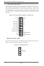
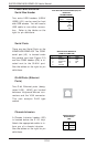
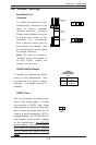
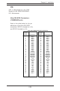
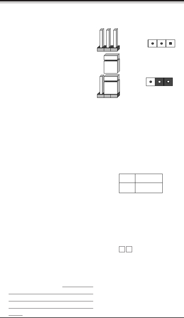
2-6 Jumper Settings
Explanation of
Jumpers
To modify the operation of the
motherboard, jumpers can be
used to choose between
optional settings. Jumpers
create shorts between two pins
to change the function of the
connector. Pin 1 is identified
with a square solder pad on
the printed circuit board. See
the motherboard layout pages
for jumper locations.
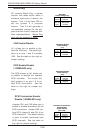
Note: On two pin jumpers,
"Closed" means the jumper is
on and "Open" means the
jumper is off the pins.
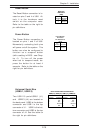
Connector
Pins
Jumper
Cap
Setting
Pin 1-2 short
3 2 1
3 2 1
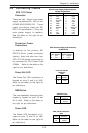
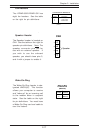
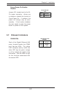
GLAN Enable/Disable
J7 enables or disables the GLAN
port(s) on the motherboard. See
the table on the right for jumper
settings. The default setting is
enabled.
Jumper
Position
Pins 1-2
Pins 2-3
Definition
Enabled
Disabled
GLAN
Enable/Disable
Jumper Settings
(J7)
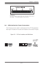
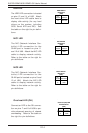
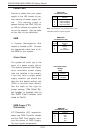
CMOS Clear
JBT1 is not literally a jumper but con-
sists of two contact pads. To clear
the contents of CMOS, short these
pads together by touching them both
with a metal conductor such as the
head of a small screwdriver. JBT1 is
located between the FPUSB4/5(J21)
and Chassis Intrusion(J25) headers
on the motherboard. For ATX/SSI
power supplies, you must completely
shut down the system and remove
the AC power cord before clearing
CMOS.
JBT1