


2-22
SUPER i2DMR-8G2/i2DMR-iG2 User's Manual
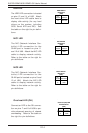
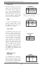
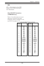
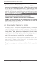
IDE Connectors
There are no jumpers to
configure the onboard IDE#1
and #2 connectors (at J37
and J35, respectively). See
the table on the right for pin
definitions.
Pin Number Function
1 Reset IDE
3 Host Data 7
5 Host Data 6
7 Host Data 5
9 Host Data 4
11 Host Data 3
13 Host Data 2
15 Host Data 1
17 Host Data 0
19 GND
21 DRQ3
23 I/O Write-
25 I/O Read-
27 IOCHRDY
29 DACK3-
31 IRQ14
33 Addr 1
35 Addr 0
37 Chip Select 0
39 Activity
Pin Number Function
2 GND
4 Host Data 8
6 Host Data 9
8 Host Data 10
10 Host Data 11
12 Host Data 12
14 Host Data 13
16 Host Data 14
18 Host Data 15
20 Key
22 GND
24 GND
26 GND
28 BALE
30 GND
32 IOCS16-
34 GND
36 Addr 2
38 Chip Select 1-
40 GND
IDE Connector Pin Definitions
(J35, J37)
2-8 COM Port, IDE, IPMI and SCSI Connections
Note the following when connecting the hard disk drive cable:
• A red mark on a wire typically designates the location of pin 1.
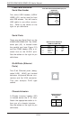
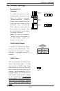
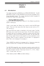
COM Port 1 (J5) & COM 2
Header (J38)
The COM Port 1 is located on J5,
and the COM 2 Header is located
on J38.