


2-16
SUPER i2DMR-8G2/i2DMR-iG2 User's Manual
Front Panel Universal
Serial Bus Header
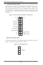
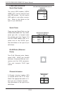
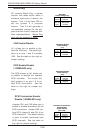
Two extra USB headers (USB4/
USB5) (J21) can be used for front
side USB access. You will need a
USB cable to use either connec-
tion. Refer to the tables on the
right for pin definitions.
Front Panel Universal Serial Bus(J21) Pin
Definitions
Pin
Number Definition
1+5V
2P0-
3P0+
4 Ground
5Key
FPUSB4/FPUSB5
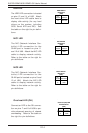
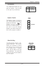
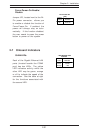
Chassis Intrusion
A Chassis Intrusion header (J25)
is located below the S I/O chip.
Attach the appropriate cable to in-
form you of a chassis intrusion.
See the tables on the right for pin
definitions.
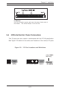
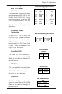
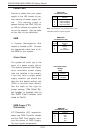
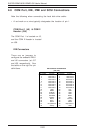
Serial Ports
There are two Serial Ports on the
i2DMR-8G2/i2DMR-iG2 The COM1
serial port (J5) is located under
the parallel port (see Figure 2-3)
and the COM2 header (J38) is lo-
cated next to the GLAN1 port.
See the tables on the right for pin
definitions.
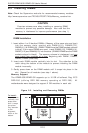
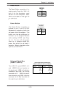
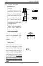
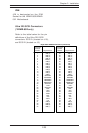
GLAN Ports (Ethernet
Ports)
Two G-bit Ethernet ports (desig-
nated LAN1, LAN2) are located
between Keyboard/Mouse con-
nectors and the VGA connector.
This port accepts RJ45 type
cables.
Serial Ports Pin Definitions
(COM1-J5, COM2-J38)
Pin Number Definition
1 DCD
2 Serial In
3 Serial Out
4 DTR
5 Ground
Pin Number Definition
6 DSR
7 RTS
8 CTS
9 RI
Pin
Number
1
2
Definition
Instrusion
Ground
Chassis Intrusion
Pin Definitions
(J25)