1-4
SUPER P4SCT/P4SCT+/P4SCT+II User’s Manual
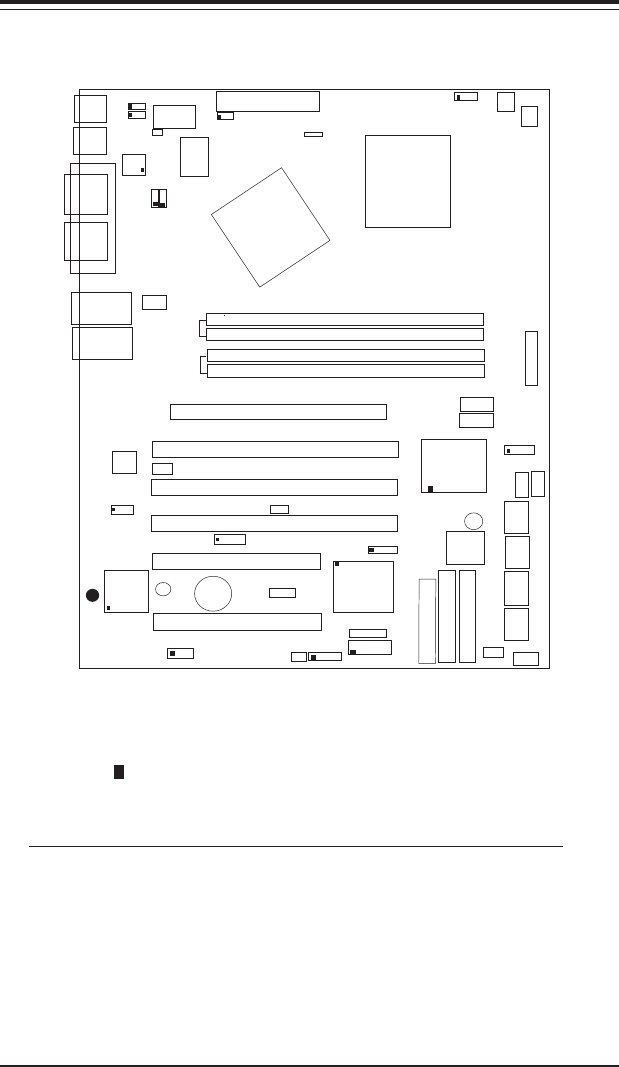
Figure 1-4. SUPER P4SCT/P4SCT+/P4SCT+II Motherboard Layout
CPU
478 PGA
MCH
PWR LED
COM2
J17
J21
J20
USB 1/2
Parallel Port
JP8
J11
JL1
JPWAKE
WOR
JP1
JP2
OH FAN/CH Fan5
COM 1
VGA
JG1
GLAN 1
PCI X-1
PCI-X 2
PCI -X 3
PCI 2
FLOPPY
BATTERY
BIOS
J2
DIMM 0A (Blue)
Watch Dog
FRONT PANEL CTR
BANK0
BANK1
®
JF1
J9
J8
WOL
IR
J10
Super I/O
J16
Speaker
J18
J37
I-SATA LED
J36
Keylock
J5
USB 3/4
J3
J4
24-pin ATX PWRConn
S
UPER P4SCT/P4SCT+/P4SCT+II
GLAN 2
PCI 1
CHS FAN3
Intel's SATA2
KB/Mouse
J13
JPUSB
J23/J24
J25/J26
JP20
LAN2 Enable(*P4SCT+ /P4SCT+II )
RAGE-XL
+12V PWR
PWR Froce On
(North Bridge)
Notes:1.*Jumpers not indicated are for test purposes only.
2. *See Chapter 2 for detailed information on jumpers, I/O
ports and JF1 front panel connections.
3. * " " indicates the location of Pin 1.
4. Use the Green Slot for ZCRChannel RAID. The blue slot is used
to identify 2-way memory interleave.
The differences between the P4SCT, the P4SCT+ and the P4SCT+II:
1)P4SCT: One GLAN, AGP, two Intel's SATA ports, Chipset:Canterwood
(875P)
2)P4SCT+: No AGP, two GLAN Connectors, Intel's SATA Controller
w/two SATA ports, Marvell's SATA Controller w/four SATA ports,
Chipset: Canterwood-ES (E7210).
3) P4SCT+II: One AGP, two GLAN Connectors, Intel's SATA
Controller w/two SATA ports, Marvell's SATA Controller w/four
SATA ports, Chipset: Canterwood (875P).
CHS FAN4
CPU Speed
CPU/CHFan1
Intel's SATA1
SATA1/5
SATA3/7SATA4/8
JS2
JS3
JS4
VGA Enable
J33
AGP Pro
J39
JX1
JX2
JX3
SMBus
J15
88SX5040CTLR
JPS1
GLAN CTLR
82541
JPL2
CLR CMOS
JBT1
6300ESB
(Hance
Rapids)
(**P4SCT/P4SCT+II)
JS1
SPKR1
M-SATA1-2 Enable
Marvell
SATA2/6
IDE1
IDE2
Ch. Intru.
J7
CHS FAN2
(Marvall's SATA)
LE2 Standby LED
LAN CTLR
82547
DIMM 1A (Blue)
DIMM 0B (Black)
DIMM 1B (Black)
Speaker
M- SATA LED
(*P4SCT+ /P4SCT+II )
JS9


