


SUPER PIIIDM6/PIIIDM4/PIIIDM3/PIIIDME User's Manual
1-14
Introduction
COM2
J14
J13
J13
PS/2 KB
PS/2 MOUSE
J10
J8
J12
USB
BT1
B
A
T
T
E
R
Y
J22
Parallel
Port
J11
FLO
PPY
12"
11.55"
PCI 1
PCI 2
PCI 3
PCI 4
ATX POWER
CPU 1
FAN
J27
®
WOL
PCI64 #2
PCI64 #1 - SISL
J9
AGP PRO
CPU 1
CPU 2
CPU 2
FAN
THRM
FAN
B
ank0
B
ank2
B
ank3
B
ank1
PWR_SEC
CH FAN
1
CH FAN
2
ID
E
#1
ID
E #2
WOR JBT1
11
JP7
JP5
1
JP3
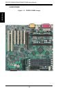
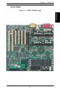
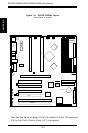
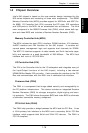
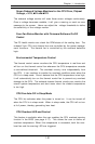
SUPER PIIIDME
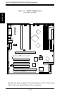
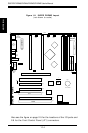
Figure 1-8. SUPER PIIIDME Layout
(not drawn to scale)
FWH
(BIOS)
CD_1 CD
J14 J15 J2 J5 J4 J3
LINE OUT
LINE IN
MIC
COM1
J38
JF1
IR Header
GAME
PORT
J28
JP12
JP13
JP4
JP11
JL1
1
Also see the figure on page 2-5 for the locations of the I/O ports and
2-6 for the Front Control Panel (JF1) connectors.
1