


Chapter 2: Installation
2-9
Installation
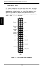
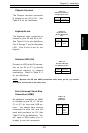
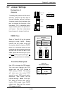
Chassis Intrusion
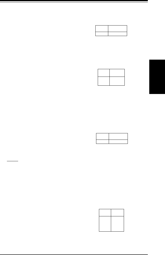
The Chassis Intrusion connection
is located on pin 20 of JF1. See
Table 2-9 for pin definitions.
Pin
Number
20
Definition
Intrusion Input
Table 2-9
Chassis Intrusion (IT)
Pin Definitions (JL1)
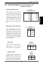
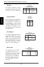
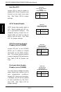
Keyboard Lock
The Keyboard Lock connection is
located on pins 22 and 24 of JF1.
See Table 2-10 for pin definitions.
Pins 5 through 7 are for the power
LED. Pins 8 and 9 are for the
keylock.
Table 2-10
Keyboard Lock
(KL) Pin Definitions
(JF1)
Pin
Number
22
24
Definition
+5V
GND
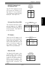
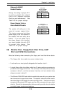
Overheat LED (OH)
Connect an LED to the OH connec-
tion on pin 26 of JF1 to provide
advanced warning of chassis
overheating. Refer to Table 2-11
for pin definitions.
Pin
Number
10
Definition
OH Active
Table 2-11
Overheat LED (OH)
Pin Definitions (JF1)
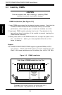
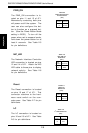
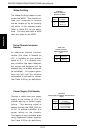
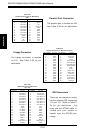
Extra Universal Serial Bus
Connection (USB0)
An additional connection for USB0
is included on pins 25, 27, 29 and
31 of JF1 for front side USB ac-
cess. You cannot have devices
connected to both this and the
back side connector at J12. See
Table 2-12 for pin definitions. You
will need a USB cable (not in-
cluded) to use this connection.
Pin
Number
1
2
3
4
Definition
+5V
Key
IRRX
Ground
Table 2-12
USB0 Pin
Definitions
NOTE: Because the OH and USB0 connectors both share pin 25, you cannot
have both connnected at the same time.