


2-18
X6DH8-G2/X6DHE-G2 User's Manual
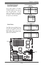
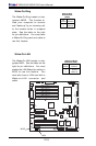
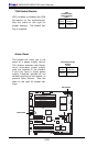
Pin
Number
1
2
3
Definition
+5V Standby
Ground
Wake-up
Wake-On-LAN Pin
Definitions (JWOL)
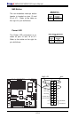
Wake-On-LAN
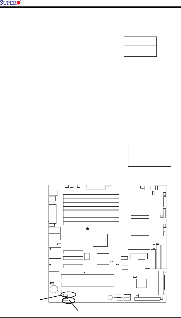
The Wake-On-LAN header is des-
ignated WOL. See the table on the
right for pin definitions. You must
enable the LAN Wake-Up setting in
BIOS to use this feature. You
must also have a LAN card with a
Wake-on-LAN connector and
cable.
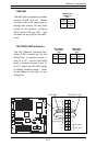
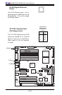
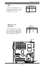
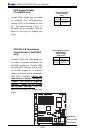
Wake-On-Ring
The Wake-On-Ring header is des-
ignated JWOR. This function al-
lows your computer to receive
and "wake-up" by an incoming call
to the modem when in suspend
state. See the table on the right
for pin definitions. You must have
a Wake-On-Ring card and cable to
use this feature.
Wake-on-Ring
Pin Definitions
(JWOR)
Pin
Number
1
2
Definition
Ground
Wake-up
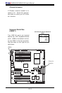
GLAN1
®
JLAN1
S
UPER X6DH8-G2
GLAN2
D
IM
M
2B
(B
an
k 2)
D
IM
M
2A
(B
an
k 2)
D
IM
M
3B
(B
an
k 3)
D
IM
M
3A
(B
ank 3)
D
IM
M
4B
(B
an
k 4)
D
IM
M
4A
(B
an
k 4)
D
IM
M
1A
(B
an
k 1)
D
IM
M
1B
(B
ank 1)
Fan1
8-pin
PWR
PWR
SMBus
JF1
FP Control
JD1
S
P
K
PW LED
JP15
Fan2JOH1
O
H
Fan8
Fan3
CH Intru
JL1
WD Enable
IPMI
IDE1
Floppy
COM2
J20
BIOS
J
W
D
JPA1
SCSI CH A
Ultra 320
S
C
S
I C
H
B
Fan4
JPA2
7902
CTRL
SATA0
SATA1
USB2/3
SMBUS
Speaker
PCI-X #1 100 M
Hz ZCR
PCI-X #2 100 MHz
PCI-X #3 133 MHz
WOR
Battery
JPL1
GLAN
CTLR
RAGE-
X
USB4
82546
GLAN
Enable
X4 PCI-Epx #4
X8 PCI-Epx #5
X8 PCI-Epx #6
J
1
2
J
1
3
J
1
4
J
1
5
J
1
6
J
1
7
Super
I/O
North
Bridge
JPG1
VGA
COM1
USB0/1
KB/
Mouse
Fan6
Fan5
ATX PWR
4-Pin
PWR
JPF
Parrallel
Port
J11
J32
24-Pin
Force PWR ON
VGA
Enable
Fan7
J24
J1D1
J1B4
R
eboot
O
pt. E
nable
JP14
J3
J
4
J
P
8
J7
SCSI
JPA3
JD2
J22
CPU 1
CPU 2
Alrm
Reset
JWOR
SCSI
Enable
SCSI CHA Term. Ena
Clr
CMOS
JBT1
ICH5R
SI/O
PXH
J9
J5
J6
J23
WOL
JWOL
JS1
JS2
U
ltra
3
2
0
JA2
JA1
IDE2
JP12
PW
Fault
JP13
3rd PS
Alarm
SCSI CHB Term. Ena
WOL
WOR