


Chapter 2: Installation
2-21
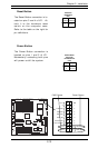
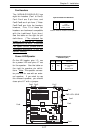
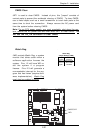
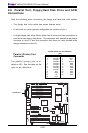
Watch Dog
JWD controls Watch Dog, a system
monitor that takes action when a
software application freezes the
system. Pins 1-2 will have WD re-
set the system if a program
freezes. Pins 2-3 will generate a
non-maskable interrupt for the pro-
gram that has frozen (requires soft-
ware implementation). Watch Dog
must also be enabled in BIOS.
Jumper
Position
Pins 1-2
Pins 2-3
Open
Definition
WD to Reset
WD to NMI
Disabled
Watch Dog
Jumper Settings (JWD)
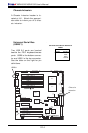
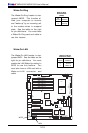
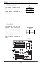
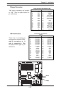
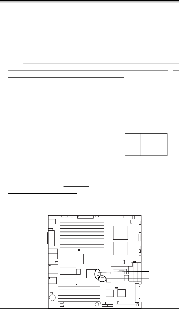
CMOS Clear
JBT1 is used to clear CMOS. Instead of pins, this "jumper" consists of
contact pads to prevent the accidental clearing of CMOS. To clear CMOS,
use a metal object such as a small screwdriver to touch both pads at the
same time to short the connection. Always remove the AC power cord
from the system before clearing CMOS.
Note: For an ATX power supply, you must completely shut down the sys-
tem, remove the AC power cord and then short JBT1 to clear CMOS. Do
not use the PW_ON connector to clear CMOS.
GLAN1
®
J
L
A
N
1
S
UPER X6DH8-G2
GLAN2
DIMM 2B (Bank 2)
DIMM 2A (Bank 2)
DIMM 3B (Bank 3)
DIMM 3A (Bank 3)
DIMM 4B (Bank 4)
DIMM 4A (Bank 4)
DIMM 1A (Bank 1)
DIMM 1B (Bank 1)
F
a
n
1
8-pin
PWR
PWR
SMBus
JF1
FP Control
JD1
S
P
K
PW LED
JP15
Fan2JOH1
O
H
F
a
n
8
Fan3
C
H
In
tru
J
L
1
W
D
E
n
a
b
le
IP
M
I
IDE1
Floppy
C
O
M
2
J
2
0
B
IO
S
J
W
D
J
P
A
1
SCSI CH A
U
ltra
32
0
S
C
S
I C
H
B
Fan4
J
P
A
2
7
9
0
2
C
T
R
L
S
A
T
A
0
S
A
T
A
1
U
S
B
2
/3
S
M
B
U
S
S
p
e
a
k
e
r
P
C
I-X
#1
1
0
0
M
H
z Z
C
R
P
C
I-X
#
2 10
0 M
H
z
P
C
I-X
#
3 13
3 M
H
z
W
O
R
B
a
tte
ry
J
P
L
1
G
L
A
N
C
T
L
R
R
A
G
E
-
X
U
S
B
4
8
2
5
4
6
G
L
A
N
E
n
a
b
le
X
4 P
C
I-E
p
x #4
X
8 P
C
I-E
p
x #5
X
8
P
C
I-E
p
x #6
J
1
2
J
1
3
J
1
4
J
1
5
J
1
6
J
1
7
S
u
p
e
r
I/O
N
o
rth
B
rid
g
e
J
P
G
1
V
G
A
C
O
M
1
U
S
B
0
/1
K
B
/
M
o
u
s
e
F
a
n
6
F
a
n
5
A
T
X
P
W
R
4
-P
in
P
W
R
JPF
Parrallel
Port
J
1
1
J
3
2
2
4
-P
in
Force PWR ON
V
G
A
E
n
a
b
le
F
a
n
7
J24
J1D1
J1B4
R
eb
o
o
t
O
pt. E
n
able
JP14
J
3
J4
J
P
8
J
7
SCSI
J
P
A
3
J
D
2
J
2
2
C
P
U
1
C
P
U
2
Alrm
Reset
J
W
O
R
SCSI
Enable
SCSI CHA Term. Ena
C
lr
C
M
O
S
J
B
T
1
IC
H
5
R
S
I/O
P
X
H
J
9
J
5
J
6
J
2
3
W
O
L
J
W
O
L
J
S
1
J
S
2
U
ltra
3
2
0
J
A
2
J
A
1
IDE2
JP12
PW
Fault
JP13
3rd PS
Alarm
SCSI CHB Term. Ena
CMOS CLR
WD