


2-22
X6DH8-G2/X6DHE-G2 User's Manual
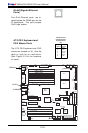
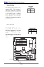
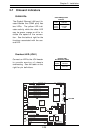
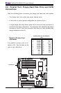
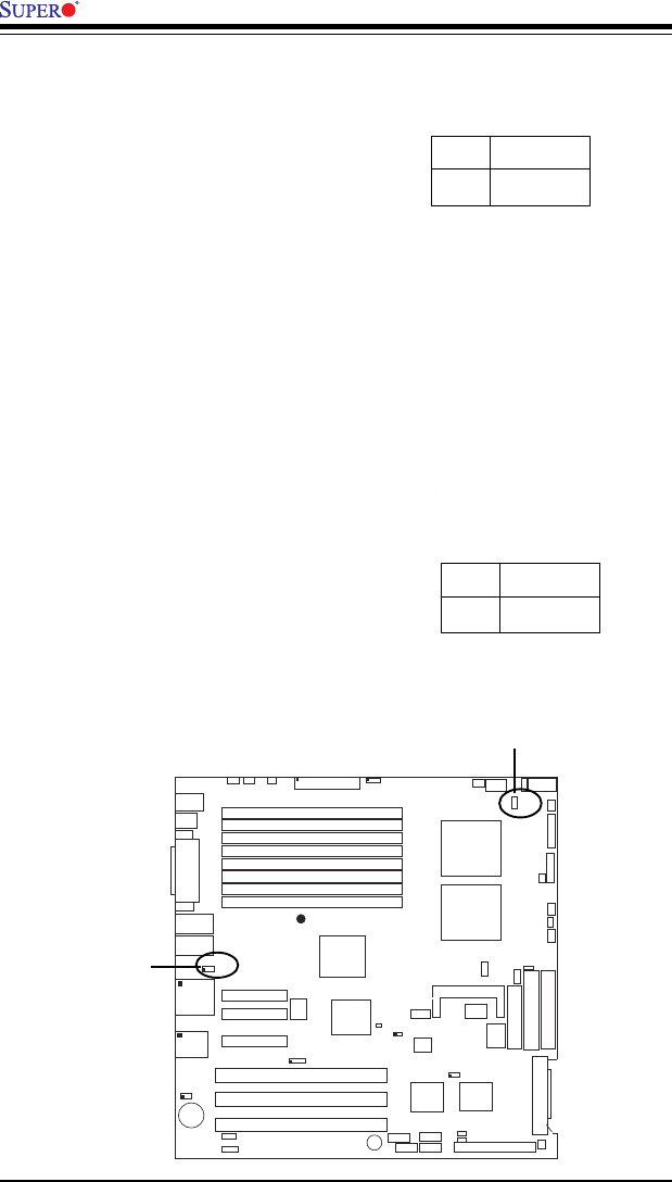
VGA Enable/Disable
JPG1 enables or disables the VGA
Connector on the motherboard.
See the table on the right for
jumper settings. The default set-
ting is enabled.
Jumper
Position
Pins 1-2
Pins 2-3
Definition
Enabled
Disabled
VGA
Enable/Disable
Jumper Settings
(JPG1)
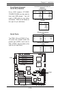
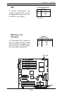
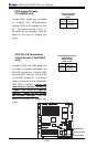
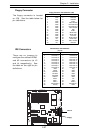
Alarm Reset
The system will notify you in the
event of a power supply failure.
This feature assumes that Super-
micro redundant power supply
units are installed in the chassis.
If you only have a single power
supply installed, please do not
connect anything to this header to
prevent false alarms. See the
table on the right for jumper set-
tings.
Jumper
Position
Open
Closed
Definition
Normal
Reset Alarm
Alarm Reset Jumper
Settings
(JP14)
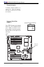
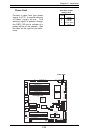
GLAN1
®
J
L
A
N
1
S
UPER X6DH8-G2
GLAN2
DIMM 2B (Bank 2)
DIMM 2A (Bank 2)
DIMM 3B (Bank 3)
DIMM 3A (Bank 3)
DIMM 4B (Bank 4)
DIMM 4A (Bank 4)
DIMM 1A (Bank 1)
DIMM 1B (Bank 1)
F
a
n
1
8-pin
PWR
PWR
SMBus
JF1
FP Control
JD1
SPK
PW LED
JP15
Fan2JOH1
O
H
Fan8
Fan3
CH Intru
JL1
WD Enable
IPMI
IDE1
Floppy
COM2
J20
BIOS
JW
D
JPA1
SCSI CH A
U
ltra
3
2
0
SCSI CH B
Fan4
JPA2
7902
CTRL
SATA0
SATA1
USB2/3
SMBUS
Speaker
P
C
I-X
#
1
1
0
0
M
H
z
Z
C
R
P
C
I-X
#
2
1
0
0
M
H
z
P
C
I-X
#
3
1
3
3
M
H
z
WOR
Battery
JPL1
GLAN
CTLR
RAGE-
X
USB4
82546
GLAN
Enable
X
4
P
C
I-E
p
x
#
4
X
8
P
C
I-E
p
x
#
5
X
8
P
C
I-E
p
x
#
6
J
12
J
13
J1
4
J
1
5
J
1
6
J1
7
Super
I/O
North
Bridge
JPG1
VGA
COM1
USB0/1
KB/
Mouse
Fan6
Fan5
ATX PWR
4-Pin
PWR
JPF
Parrallel
Port
J11
J32
24-Pin
Force PWR ON
VGA
Enable
Fan7
J24
J1D1
J1B4
Reboot
Opt. Enable
JP14
J3
J4
JP8
J7
SCSI
JPA3
JD2
J22
CPU 1
CPU 2
Alrm
Reset
JWOR
SCSI
Enable
SCSI CHA Term. Ena
Clr
CMOS
JBT1
ICH5R
SI/O
PXH
J9
J5
J6
J23
WOL
JWOL
JS1
JS2
U
ltra
3
2
0
JA2
JA1
IDE2
JP12
PW
Fault
JP13
3rd PS
Alarm
SCSI CHB Term. Ena
VGA Enable
Alarm Reset