


Chapter 1: Introduction
1-5
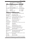
Quick Reference ( X7DB8/X7DBE)
Jumper Description Default Setting
J27, J28 I
2
C Bus to PCI-X/PCI-E Slots Open (Disabled)
J3P 3rd PWR Failure Detect Off (Disabled)
JBT1 CMOS Clear See Chapter 2
JCF1 Compact Card Master/Slave Select On (Master)
JPA1 (*X7DB8) SCSI Controller Enable Pins 1-2 (Enabled)
JPA2, JPA3 SCSI CHA(JPA2),CHB(JPA3)Term.En Off (Enabled) (*X7DB8)
JPG1 VGA Enable Pins 1-2 (Enabled)
JPL1/ JPL2 GLAN1/GLAN2 Enable Pins 1-2 (Enabled)
JWD Watch Dog Pins 1-2 (Reset)
Connector Description
ATX PWR (JPW1) Primary 24-Pin ATX PWR Connector
Aux. PWR/CPU PWR +12V 4-pin PWR (JWP2)/+12V 8-pin PWR(JPW3)
Alarm Reset (JAR) Alarm Reset Off (Normal)
Chassis Intrusion (JL1) Chassis Intrusion Header
COM1/COM2 COM1/COM2 Serial Port Connectors
Compact PWR (JWF1) Compact Card PWR Connector (*Used if JCF1 is on.)
DA1/DA2 SCSI Activity LED Indicators (See Chapter 2)
DIMM#1A-DIMM#4B Memory FBD DDRII Slots
FAN 1-8 Fans 1-8 (CPU Fans/Chassis Fans)
Floppy (J22) Floppy Disk Drive Connector
FP CTRL (JF1) Front Control Panel Connector
GLAN 1/2 (JLAN1/2) G-bit Ethernet Ports
IDE1/IDE2 (Note) IDE1 Hard Drive (JIDE1)/Compact Flash Card (JIDE2)
Keylock (JK1) Keylock Header
OH LED (JOH1) Overheat LED
Parallel (J21) Parallel (Printer) Port
PSF Power Supply Failure (See Chapter 2)
PWR LED (LE1) PWR LED Indicator (Note 6 on Pg.1-4)
PWR LED/SPKR (JD1) PWR LED(pins1-3)/SpeakerHeader (pins 4-7)
PWR SMB (J17) Power System Management (I
2
C) Header
SATA0-SATA5 SATA 0-5 Connectors
SCSI Chan. A/B(JA1/JA2)SCSI Channel A/Channel B Connectors (*X7DB8 only)
SGPIO 1/2(J29,J30) Serial General Purpose Input/Output Headers
SMB (J18) System Management Bus Header
Slot 7 SIM Low Profi le IPMI Connector
USB 0/1,USB 2/3, USB4 Back Panel USB 0/1, Front Panel USB 2/3, FP USB4
VGA (J15) VGA Connector
WOL (JWOL) Wake-on-LAN Header
WOR (JWOR) Wake-on-Ring Header
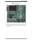
Note: JIDE2 is for Compact Card Use only. For Compact Card to work properly,
please enable JCF1 by putting cap on it and connect JWF1 to a power supply.