


2-18
X7DB8/X7DBE User's Manual
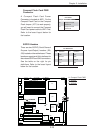
GLAN1
®
JLAN1
S
UPER X7DB8/E
GLAN2
Fan1
8-pin PWR
FP Ctrl
SPK
PW LED
JOH1
Fan3
IDE1
Floppy
BIOS
320 SCSI Channel A
Fan4
SATA1
SATA0
USB2/3
SMB
PCI-X 100 MHz ZCR
PCI-X 133 MHz
JWD
Battery
VGA
PCI-Exp x8
North Bridge
VGA
COM1
USB0/1
KB/
Mouse
Fan6
Fan5
ATX PWR
4-Pin
PWR
J3P
Parrallel
Port
24-Pin
JPG1
SCSI CTRL
CPU1
CPU2
South
Bridge
PXH
DIMM 1A (Bank 1)
Fan7
JAR
PSF
Fan2
Compact Flash
LE1
Fan8
JCF1
JWF1
JPA2
JPA3
JPA1
320 SCSI Channel B
SATA3
SATA2
SATA4
SATA5
JL1
JK1
Slot1
Slot2
Slot3
PCI-X 133 MHz
Slot4
JPL1
JPL2
Slot5
PCI-Exp x4
Slot6
PCI-Exp x8
SEPC
SIMLP IPMI
Slot7
DIMM 1B (Bank 1)
DIMM 2A (Bank 2)
DIMM 2B (Bank 2)
DIMM 3A (Bank 3)
DIMM 3B (Bank 3)
DIMM 4A (Bank 4)
DIMM 4B (Bank 4)
JBT1
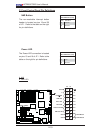
USB4
JWOR
JCOM2
DA2
WOL
DA1
S I/O
JP1
LAN
CTRL
J27
J28
SGPIO1
SGPIO2
SMB PS
CTRL
J7
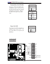
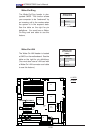
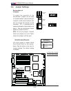
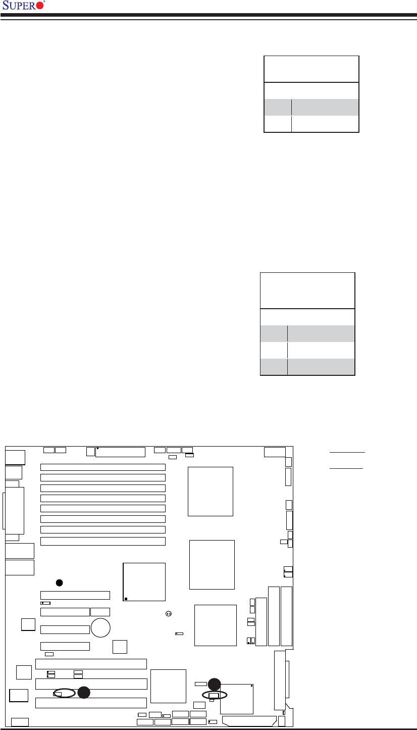
Wake-On-Ring
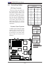
The Wake-On-Ring header is des-
ignated JWOR. This function allows
your computer to be "awakened" by
an incoming call to the modem when
the system is in the suspend state.
See the table on the right for pin
defi nitions. You must have a Wake-
On-Ring card and cable to use this
feature.
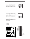
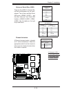
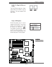
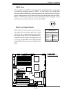
Wake-On-LAN
The Wake-On-LAN header is located
at JWOL on the motherboard. See the
table on the right for pin defi nitions.
(You must also have a LAN card with
a Wake-On-LAN connector and cable
to use this feature.)
Wake-On-Ring
Pin Defi nitions
Pin# Defi nition
1 Ground
2 Wake-up
Wake-On-LAN
Pin Defi nitions
(JWOL)
Pin# Defi nition
1 +5V Standby
2 Ground
3 Wake-up
A
B
A. WOR
B. WOL