


Chapter 2: Installation
2-19
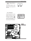
GLAN1
®
JLAN1
S
UPER X7DB8/E
GLAN2
Fan1
8-pin PWR
FP Ctrl
SPK
PW LED
JOH1
Fan3
IDE1
Floppy
BIOS
320 SCSI Channel A
Fan4
SATA1
SATA0
USB2/3
SMB
PCI-X 100 MHz ZCR
PCI-X 133 MHz
JWD
Battery
VGA
PCI-Exp x8
North Bridge
VGA
COM1
USB0/1
KB/
Mouse
Fan6
Fan5
ATX PWR
4-Pin
PWR
J3P
Parrallel
Port
24-Pin
JPG1
SCSI CTRL
CPU1
CPU2
South
Bridge
PXH
DIMM 1A (Bank 1)
Fan7
JAR
PSF
Fan2
Compact Flash
LE1
Fan8
JCF1
JWF1
JPA2
JPA3
JPA1
320 SCSI Channel B
SATA3
SATA2
SATA4
SATA5
JL1
JK1
Slot1
Slot2
Slot3
PCI-X 133 MHz
Slot4
JPL1
JPL2
Slot5
PCI-Exp x4
Slot6
PCI-Exp x8
SEPC
SIMLP IPMI
Slot7
DIMM 1B (Bank 1)
DIMM 2A (Bank 2)
DIMM 2B (Bank 2)
DIMM 3A (Bank 3)
DIMM 3B (Bank 3)
DIMM 4A (Bank 4)
DIMM 4B (Bank 4)
JBT1
USB4
JWOR
JCOM2
DA2
WOL
DA1
S I/O
JP1
LAN
CTRL
J27
J28
SGPIO1
SGPIO2
SMB PS
CTRL
J7
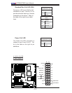
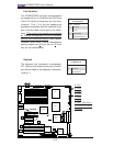
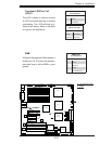
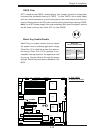
Power LED/Speaker
On the JD1 header, pins 1-3 are for
a power LED and pins 4-7 are for the
speaker. See the table on the right
for speaker pin definitions. Note:
The speaker connector pins are for
use with an external speaker. If you
wish to use the onboard speaker, you
should close pins 6-7 with a jumper.
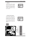
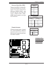
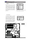
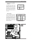
GLAN 1/2 (Giga-bit Ethernet
Ports)
Two G-bit Ethernet ports are desig-
nated JLAN1 and JLAN2 on the IO
backplane. This port accepts RJ45
type cables.
Speaker Connector
Pin Defi nitions
Pin Setting Defi nition
Pins 6-7 Internal Speaker
Pins 4-7 External Speaker
A
B
A. GLAN1/2
B. PWR LED/Speaker
GLAN1 GLAN2