


2-14
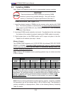
X7DB8/X7DBE User's Manual
In
troduction
GLAN1
®
JLAN1
S
UPER X7DB8/E
GLAN2
Fan1
8-pin PWR
FP Ctrl
SPK
PW LED
JOH1
Fan3
IDE1
Floppy
BIOS
320 SCSI Channel A
Fan4
SATA1
SATA0
USB2/3
SMB
PCI-X 100 MHz ZCR
PCI-X 133 MHz
JWD
Battery
VGA
PCI-Exp x8
North Bridge
VGA
C
OM1
U
SB0/1
K
B/
M
ouse
Fan6
Fan5
ATX PWR
4-Pin
PWR
J3P
Parrallel
Port
24-Pin
JPG1
SCSI CTRL
CPU1
CPU2
South
Bridge
PXH
DIMM 1A (Bank 1)
Fan7
JAR
PSF
Fan2
Compact Flash
LE1
Fan8
JCF1
JWF1
JPA2
JPA3
JPA1
320 SCSI Channel B
SATA3
SATA2
SATA4
SATA5
JL1
JK1
Slot1
Slot2
Slot3
PCI-X 133 MHz
Slot4
JPL1
JPL2
Slot5
PCI-Exp x4
Slot6
PCI-Exp x8
SEPC
SIMLP IPMI
Slot7
DIMM 1B (Bank 1)
DIMM 2A (Bank 2)
DIMM 2B (Bank 2)
DIMM 3A (Bank 3)
DIMM 3B (Bank 3)
DIMM 4A (Bank 4)
DIMM 4B (Bank 4)
JBT1
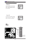
USB4
JWOR
JCOM2
DA2
WOL
DA1
S I/O
JP1
LAN
CTRL
J27
J28
SGPIO1
SGPIO2
SMB PS
CTRL
J7
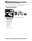
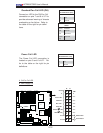
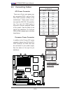
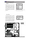
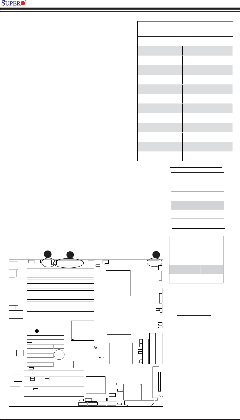
2-5 Connecting Cables
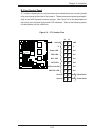
ATX Power Connector
There are a 24-pin main power sup-
ply connector(JPW1) and an 8-pin
CPU PWR connector (JPW3) on the
motherboard. These power connec-
tors meet the SSI EPS 12V specifi ca-
tion. The 4-pin 12V PWR supply is
required to provide adequate power
to the system. See the table on the
right for pin defi nitions. For the 8-pin
PWR (JPW3), please refer to the item
listed below.
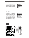
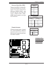
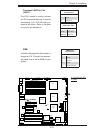
Processor Power Connector
In addition to the Primary ATX power
connector (above), the 12V 8-pin CPU
PWR connector at JPW3 must also
be connected to your power supply.
See the table on the right for pin
defi nitions.
ATX Power Connector
Pin Defi nitions
Pin# Defi nition Pin # Defi nition
13 +3.3V 1 +3.3V
14 -12V 2 +3.3V
15 COM 3 COM
16 PS_ON 4 +5V
17 COM 5 COM
18 COM 6 +5V
19 COM 7 COM
20 Res (NC) 8 PWR_OK
21 +5V 9 5VSB
22 +5V 10 +12V
23 +5V 11 +12V
24 COM 12 +3.3V
Required Connection
Required Connection
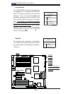
12V 4-pin Power Con-
nector
Pin Defi nitions
Pins Defi nition
1 and 2 Ground
3 and 4 +12V
12V 8-pin Power CPU
Connector
Pin Defi nitions
Pins Defi nition
1 through 4 Ground
5 through 8 +12V
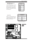
A. 24-pin ATX PWR
B. 8-pin Processor PWR
C. 4-pin PWR
A
B
C