– 13 –
CXP854P60
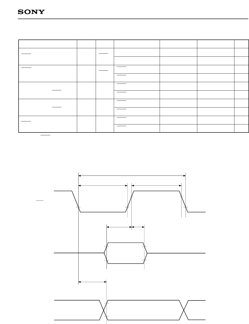
(2) Serial transfer (Ta = –10 to +75°C, VDD = 4.5 to 5.5V, Vss = 0V)
Item
SCK cycle time
tKCY
SCK
Input mode
Output mode
SCK input mode
SCK output mode
SCK input mode
SCK output mode
SCK input mode
SCK output mode
SCK input mode
SCK output mode
1000
8000/fc
400
4000/fc – 50
100
200
200
100
200
100
ns
ns
ns
ns
ns
ns
ns
ns
ns
ns
SCK
SI
SI
SO
tKH
tKL
tSIK
tKSI
tKSO
SCK
high and low level widths
SI input set-up time
(referenced to SCK ↑)
SI input hold time
(referenced to SCK ↑)
SCK ↓→SO delay time
System Pin Condition Min. Max. Unit
Note) For SCK output mode, in addition to output delay time SO capacitance must be 50pF + 1TTL.
Fig. 4. Serial transfer timing
0.2VDD
0.8VDD
tKL tKH
SO
tKCY
tSIK
tKSI
0.2VDD
0.8VDD
tKSO
0.2VDD
0.8VDD
Output data
Input data
SI
SCK


