Chapter 1 Getting Started
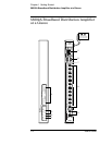
58502A Broadband Distribution Amplifier at a Glance
User’s Guide 1-3
NOTE See Chapter 3, “Features and Functions,” for a detailed discussion of
the items described below.
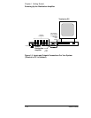
1 When the Power indicator lights, it
indicates that the proper input
power is supplied to the 58502A.
2 When the Alarm indicator lights, it
indicates that operation is no
longer normal. One or more outputs
are at fault, or input signals are
absent at both inputs A and B.
3 When the Input A or B indicator
lights, it indicates that an input
signal is present at input A or B.
4 When any of the OUTPUT STATUS
1-12 indicators light, it indicates the
associated output is functioning.
5 AC Input power jack.
6 RS232 serial interface port allows
you to remotely control and monitor
the 58502A. Its communication
language is SCPI. The connector is
a DTE configuration DE-9P (male).
7 ALARM/STATUS port is a DE-9P (male)
connector. This port allows you to
receive an alarm or input an alarm.
8 OUTPUTS 1-12 50Ω BNC output signal
ports.
9 INPUTS A and B 50Ω BNC ports allow
two input signal connections to the
58502A. The internal circuitry
selects one of these signals for
distribution.


