83-507-5002 Rev. B
63
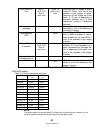
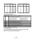
Table 7-6: OVP programming range Table 7-7: UVL programming range
Model
Rated Output Voltage
(V)
Minimum
(V)
Maximum
(V)
Model
Rated Output Voltage
(V)
Minimum
(V)
Maximum
(V)
6
0.5
7.50
6
0
5.70
8
0.5
10.0
8
0
7.60
12.5
1.0
15.0
12.5
0
11.9
20
1.0
24.0
20
0
19.0
30
2.0
36.0
30
0
28.5
40
2
.0
44.0
40
0
38.0
60
5.0
66.0
60
0
57.0
80
5.0
88.0
80
0
76.0
100
5.0
110.0
100
0
95.0
150
5.0
165.0
150
0
142
300
5.0
330.0
300
0
285
600
5.0
660.0
600
0
570
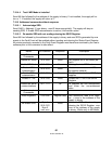
7.10.6 Status Control Commands
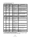
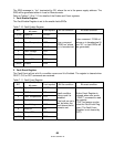
Refer to Section 7-8 for definition of the registers.
# Command Description
1 STT? Reads the complete power supply status.
Returns ASCII characters representing the following data, separated by commas:
MV<actual (measured) voltage> PC<programmed (set) current>
PV<programmed (set) voltage> SR<status register, 2-digit hex>
MC<actual (measured) current> FR<fault register, 2-digit hex>
Example response: MV(45.201),PV(45), MC(4.3257), PC(10), SR(30), FR(00)
2
FLT?
Reads Fault Conditional Register. Returns 2
-
digit hex.
3
FENA
Set Fault Enable Register using 2
-
digit hex.
4
FENA?
Reads Fault Enable Register. Returns 2
-
digit hex.
5
FEVE?
Reads Fault Event Register. Returns 2
-
digit hex. Clears bits of Fault Event Register.
6
STAT?
Reads Status Conditional Register. Retur
ns 2
-
digit hex.
7
SENA
Sets Status Enable Register using 2
-
digit hex.
8
SENA?
Reads Status Enable Register. Returns 2
-
digit hex.
9
SEVE?
Reads Status Event register. Returns 2
-
digit hex. Clears bits of Status Event register.
7.11 STATUS, ERROR AND SRQ REGISTERS
7.11.1 General Description
This Section describes the various status error and SRQ registers structure. The registers can be
read or set via the RS232/RS485 commands. When using the IEEE option, refer to the User’s
Manual for Genesys
TM
Power Supply IEEE Programming Interface.
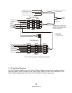
Refer to Fig. 7-7 for the Status and Error Registers Diagram.


