


Data Sheet: Maxeta
TM
iFA Series
©2002-2006 TDK Innoveta Inc.
iFA 28V 600W Advance Datasheet 8/3/2006
℡
(
877
)
498-0099
16/19
The output voltage can also be adjusted
within the same range by applying external
voltage at the trim pin via a buffer. In this
case, Vo_d can be approximately
determined by the following formula:
Vo_d ≅ Trim Terminal Voltage × Vo,nom
Contact Innoveta for more details on the
voltage trim using an external source.
The maximum power available from the
power module is fixed. As the output
voltage is trimmed up, the maximum output
current must be decreased to maintain the
maximum rated power of the module.
As the output voltage is trimmed, the output
over-voltage set point is not adjusted.
Trimming the output voltage too high may
cause the output over voltage protection
circuit to be triggered.
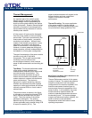
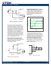
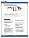
Remote Sense: The power modules
feature remote sense to compensate for the
effect of output distribution drops. The
maximum voltage allowed between the
output power terminals and output sense
terminals is 0.5V. If the remote sense
feature is not being used, the sense(+)
terminal should be connected to the Vo(+)
terminal and the sense(-) pin should be
connected to the Vo(-) pin.
The output voltage at the Vo(+) and Vo(-)
pins can be increased by either the remote
sense or the output voltage adjustment
feature. The maximum voltage increase
allowed is the larger of the remote sense
range or the output voltage adjustment
range; it is not the sum of both.
As the output voltage increases due to the
use of the remote sense, the maximum
output current must be decreased for the
power module to remain below the
maximum rated power of the module.
Power Good: Normal or abnormal
operation of the power module can be
monitored using the power good signal. The
power good pin provides an open collector
signal referenced to the output sense (-) pin
that is pulled low during normal operation of
the power module. The power good circuitry
will pull the power good pin below 1V while
sinking a maximum sink current of 5mA.
The maximum allowed voltage to the pin is
35V. In order for the power good to pull low,
the following conditions must all be met:
- None of the power module’s protection
features have been tripped; the protection
features include over-voltage, over-
current, and over-temperature protection.
- The internal bias voltage is present.
- The internal PWM drive signal is present.
- The output voltage is approximately
between 90% and 115% of Vo,nom.
When these conditions are not met, the
maximum voltage that will appear at the
output of the power good pin can be up to
50V. The typical impedance from the power
good pin to ground is greater than 500KΩ.
Power Good signal may give invalid signal
during the following conditions:
- Operation of over-current protection
- Light load condition at parallel operation
- Dynamic load operation
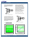
Parallel Operation: The iFA series power
modules are capable of sharing the load
current when multiple units are connected in
parallel. The load sharing technique used is
the democratic load share scheme. By
connecting the PC (or Ishare) pin of each
power module with single wire, the output
load current can be equally drawn from each
module. The voltage at PC pin will range
from 0 to 2V, referenced to the output side
sense(-). All modules in parallel should be
referenced to the same ground with good
ground plane.
By setting the output voltage accuracy of
each power module in a parallel operation to
within ±1%, the load share circuit within the
module will force the load current to be
shared equally among the multiple modules
with ±10% accuracy or better from 50% to
100% of the rated load. The maximum
output power rating of each module shall not
be exceeded.