Data Sheet: Maxeta
TM
iFA Series
©2002-2006 TDK Innoveta Inc.
iFA 28V 600W Advance Datasheet 8/3/2006
℡
(
877
)
498-0099
5/19
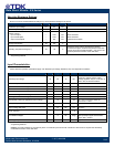
Absolute Maximum Ratings:
Stress in excess of Absolute Maximum Ratings may cause permanent damage to the device.
*Engineering Estimate
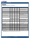
Input Characteristics:
Unless otherwise specified, specifications apply over all Rated Input Voltage, Resistive Load, and Temperature conditions.
Characteristic Min Typ Max Unit Notes & Conditions
Operating Input Voltage 36 48 75 Vdc
When 36V ≤ Vin < 38V, the modules will
continue to operate, but the output
voltage regulation may be out of spec at
load > 90% of full load condition
Maximum Input Current --- 18 20* A Vin = 0 to Vin,max
Input Low End Turn-on Voltage --- 34.9 36 Vdc
Input Low End Turn-off Voltage 30* 32.3 36 Vdc
Hysteresis --- 2.5 --- Vdc
Input Over-voltage Turn-off Voltage --- 79.5 83* Vdc
Input High End Turn-on Voltage 75 78 --- Vdc
Startup Delay Time from application of input voltage --- 10 --- mS
Vo = 0 to 0.1*Vo,nom; on/off =on,
Io=Io,max, Tc=25˚C
Startup Delay Time from on/off --- 10 --- mS Vin = Vin,nom, Io=Io,max, Tc=25˚C
Output Voltage Rise Time --- 45 60* mS
Io=Io,max, Vo=0.1 to 0.9*Vo,nom,
Tc=25˚C
Inrush Transient --- --- 1 A
2
S
Input Reflected Ripple --- 8 20* mApp
Vin=Vin,nom, Io=Io,max (0 to 20MHz)
See input/output ripple measurement
figure; BW = 20 MHz
Input Ripple Rejection --- 35 --- dB @120Hz
* Engineering Estimate
Caution: The power modules are not internally fused. An external input line fuse with a maximum value of 20A is required. See the Safety
Considerations section of the data sheet.
Characteristic Min Max Unit Notes & Conditions
Continuous Input Voltage -0.5 80 Vdc
Transient Input Voltage --- 100 Vdc 100mS max.
Isolation Voltage
Input to Output
Input to Base-plate
Output to Base-plate
---
---
---
1500
1500
500
Vdc
Vdc
Vdc
Basic Insulation
Basic Insulation
Operational Insulation
Storage Temperature -55 125 ˚C
Operating Temperature Range (Tc) -40 115 ˚C
Measured at the location specified in the thermal
measurement figure; maximum temperature varies with
output current and module orientation – see curve in the
thermal performance section of the data sheet.


