


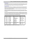

Chapter 4 – SocketModem Parallel Interface – A Programmer’s Description
SocketModem Global MT5634SMI Developer’s Guide 21
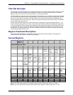
LSR Line Status
Bit 7: Error in RX FIFO. This bit is always set to 1 if at least one data byte in the RX FIFO has an error.
This will clear when there are no more errors in the RX FIFO.
Bit 6: Transmitter empty. This bit is the same as LSR bit 5 (THRE) in MMM
Bit 5: Transmitter holding register empty. This bit is set to 1 when either the transmitter holding register
has been read (emptied) by the micro-controller (16450 mode) or the TX FIFO is empty (16550
mode). This bit is set to 0 when either the THR or the TX FIFO becomes not empty in 16450 mode.
In 16550 mode, it is set to 0 only after the trigger level has been met since the last occurrence of
TX FIFO empty. If the transmitter timer is enabled, a shadow bit exists which delays the timer
setting this bit to 1. When reading this bit, the micro-controller will not see the delay. Both shadow
and register bits are cleared when the host writes to the THR or TX FIFO in 16450 mode. The
trigger level must be reached to clear the bit in 16550 (FIFO) mode.
Bits 2–4: Used for parity error, framing error, and break detect. These bits are written, indirectly, by the
micro-controller as follows: The bits are first written to the shadow bit locations when the micro-
controller write accesses the LSR. When the next character is written to the receive buffer (RBR) or
the RX FIFO, the data in the shadow bits is then copied to the RBR (16450 mode) or RX FIFO
(16550 mode). In FIFO mode, bits become available to the host when the data byte associated with
the bits is next to be read. In FIFO mode, with successive reads of the receiver, the status bits will
be set if an error occurs on any byte. Once the micro-controller writes to the RBR or RX FIFO, the
shadow bits are auto cleared. The register bits are updated with each host read.
Bit 1: Overrun error. This bit is set if the micro-controller makes a second write to RBR before the host
reads data in the buffer (16450 mode) or with a full RX FIFO (16550 mode). No data will be
transferred to the RX FIFO under these circumstances. This bit is reset when the host reads the
LSR.
Bit 0: Data ready bit. This bit is set to 1 when received data is available, either in the RX FIFO (16550
mode) or the RBR (16450 mode). This bit is set immediately upon the micro-controller writing data
to the RBR or FIFO if the receive timer is not enabled, but it is delayed by the timer interval if the
receive timer is enabled. For micro-controller read access, a shadow bit exists so that the micro-
controller does not see the delay that the host sees. Both bits are cleared to logic 0 immediately
upon reading all data in either RBR or RX FIFO.
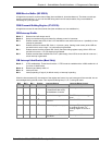
MSR Modem Status
Bits 4 through 7 of the MSR can also take on the MCR bits 0 through 3 value when in MCR loop mode (i.e. when
MCR b4 = 1). The transfer of bits in loop back has a null modem twist (i.e. MCR b0 goes to MSR b5 and MCR
b1goes to MSR b4).
Bit 7: Data carrier detect (DCD) bit.
Bit 6: Ring indicator (RI) bit.
Bit 5: Data set ready (DSR) bit.
Bit 4: Clear to send (CTS) bit.
Bit 3: Delta data carrier detect pin. This bit is set to a 1 whenever the data carrier detect bit changes
state. It is reset when the host reads the modem status register.
Bit 2: Trailing edge ring indicator bit. This bit is set to 1 on the falling edge of the ring indicator bit. It is
reset when the host reads the modem status register.
Bit 1: Delta data set ready bit. This bit is set to 1 whenever the data set ready changes state. It is reset
when the host reads the modem status register.
Bit 0: Delta clear to send bit. This bit is a one whenever the clear to send bit changes state. It is reset
when the host reads the modem status register.