


Getting Started
PS280 & PS283 User Manual
7
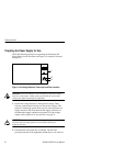
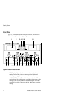
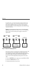
17. Output Terminals. These terminals for the right, variable power
supply allow you to plug in the test leads as follows:
H The red terminal on the right is the positive polarity output
terminal. It is indicated by a plus (+) sign above it.
H The black terminal on the left is the negative polarity output
terminal. It is indicated by a minus (–) sign above it.
H The green terminal in the middle is the earth and chassis
ground.
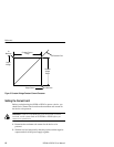
18. C.C. Indicator. If this is lighted, the power supply is producing a
constant current. See Figure 3 on page 10 for an illustration of the
constant voltage/constant current crossover point.
19. C.V. Indicator. If this is lighted, the power supply is producing a
constant voltage. See Figure 3 on page 10 for an illustration of
the constant voltage/constant current crossover point.
20. VOLTAGE Knob. Allows you to set the output voltage for the
right variable power supply. If the instrument is in a tracking
mode, the right power supply is the master and the VOLTAGE
knob affects both variable power supplies.
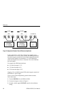
21. Output Terminals. These terminals for the 5 V FIXED power
supply allow you to plug in the test leads as follows:
H The red terminal on the right is the positive polarity output
terminal.
H The black terminal on the left is the negative polarity output
terminal.
22. The overload indicator lights when the current on the 5 V FIXED
power supply becomes too large.