Reference
24
PS280 & PS283 User Manual
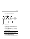
5V FIXED 3A
-+GND
-+GND
SLAVE MASTER
Load 1
0 to +30 V
INTERNAL
0 to 4 A (PS280)
0 to 2 A (PS283)
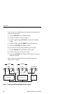
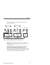
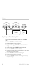
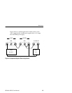
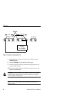
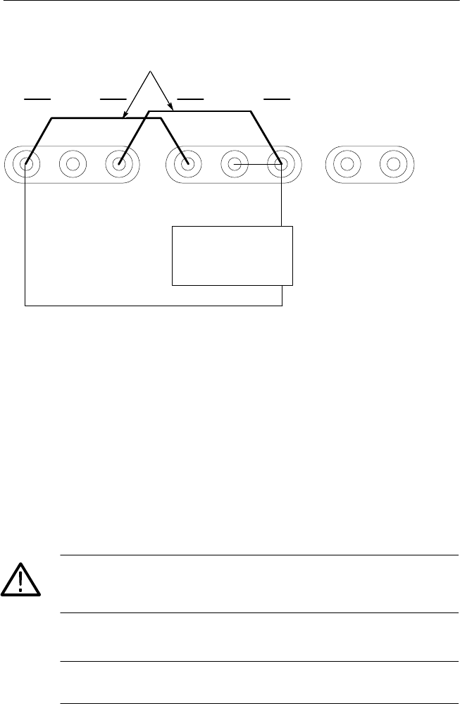
Figure 14: Parallel Tracking Application
7. Adjust the output voltage to the desired level using the master
VOLTAGE knob.
8. Turn the POWER off to the PS280 or PS283 again.
9. Connect the positive polarity of the device being powered to the
positive master terminal.
10. Connect the negative polarity of the device being powered to the
negative master terminal.
CAUTION. To prevent damage to the PS280 or PS283, do not attempt
to obtain output simultaneously from both variable power supplies
while in parallel tracking mode.
NOTE. The 5 V FIXED supply can be independently grounded or
allowed to float.


